
 Inglese
 中文简体
中文简体 Русский
 Español
 Português
 Türkçe
 العربية
 Deutsch
 Polski
 Italiano
 Français
 한국어
한국어 ไทย
ไทย Tiếng Việt
 日本語
日本語





























Goniofotometro per lampade automobilistiche e semaforiche
Manuale d'uso
Applicabile LISUN modelli: LSG-1950S
1. Disimballaggio e nozioni di base sull'apparecchiatura
1.1 Unboxing e ispezione
Quando si disimballa il dispositivo, maneggiarlo con delicatezza per evitare di graffiare l'involucro esterno con strumenti appuntiti. Dopo averlo disimballato, ispezionare innanzitutto l'esterno del dispositivo per assicurarsi che non vi siano deformazioni o ammaccature visibili e che i pulsanti non siano danneggiati o allentati. Se si notano anomalie con il dispositivo o i suoi accessori, non accenderloVi preghiamo di contattarci immediatamente.
1.2 System Configuration and Overview
Note: The table below lists the core hardware components of the entire system. The equipment you purchased may include only a portion of these components; please keep this in mind when following the instructions in this manual.
| Nome Componente | Modello | Caratteristiche principali |
|---|---|---|
| Unità principale del goniofotometro | LSG-1950S | Used in conjunction with a photometric probe to measure photometric parameters and their spatial distribution |
| Sonda di luminanza | PM400C(N) | Used to test photometric parameters |
| Luce standard | SLS-150W | Utilizzato per calibrare la camera oscura (sonda di luminanza) |
| Apparecchiature specializzate | / | Used to hold samples |
| Laser a linee incrociate | / | Utilizzato durante l'installazione e la messa in servizio; utilizzato durante la calibrazione e il collaudo per determinare la posizione e l'orientamento della lampada standard e dell'apparecchio di illuminazione campione. |
| Mobile | CASE-19 | Used to house an angle controller, a power meter, and DC and AC power supplies. Includes a power strip, an RS-485 communication module, and other components. |
| Regolatore di angolo | RT-200C | The angle at which the Goniophotomoeter is displayed and controlled. Generally, no manual operation is required; it can be controlled using the software. |
| Misuratore di potenza | Serie LS | Misurare i parametri elettrici quali tensione, corrente, potenza e fattore di potenza del campione. |
| Generatore di corrente continua | Serie DC | Fornisce un'alimentazione CC stabile per campioni CC, lampade standard e lampade ausiliarie. |
| Alimentazione AC | Serie LSP | Fornisce un alimentatore CA stabile e a onda sinusoidale pura per campioni CA |
1.3 Key Specifications of the Goniophotomoeter Main Unit
| Progetto | Note: |
|---|---|
| Vertical Axis Rotation Angle | -90° to +90° |
| Horizontal Axis Rotation Angle | -35° to +35° |
| Precisione angolare | 0.1° |
| Risoluzione angolare | 0.01° |
| Sonda di luminanza | CIE Class A (Standard) Accuracy |
| Standard applicabili | GB 13954 “Signal Lamps for Special-Purpose Vehicles”; GB 25991 “LED Headlamps for Motor Vehicles”; FMVSS 108 “Lamps, Reflectors, and Auxiliary Equipment”; ECE-R65 “Regulations Concerning Special Warning Devices” |
2. Note importanti
2.1 Sicurezza Impianti elettrici
Il sistema deve essere collegato a una fonte di alimentazione CA stabile di 220 V ±5%, con una frequenza di 50 Hz o 60 Hz, e deve essere garantita una corretta messa a terra con una resistenza di terra ≤4 Ω. Non utilizzare l'apparecchiatura se i collegamenti di alimentazione sono allentati o i cavi sono danneggiati.
2.2 Sicurezza ambientale
When using an optical darkroom, the ambient temperature must be maintained at 25±1°C, and the relative humidity must be maintained between 10% and 65% RH;
Sia la sala di controllo che la camera oscura devono essere mantenute asciutte, ben ventilate, prive di polvere e di gas corrosivi;
Evitare di posizionare il dispositivo vicino a forti campi magnetici o elettrici; deve essere posizionato su una superficie piana e stabile.
2.3 Darkroom Operating Procedures
2.3.1 Descrizione della camera oscura
Vi preghiamo di confermare che la camera oscura sia stata realizzata esattamente secondo i disegni che vi abbiamo fornito. Qualora si riscontrassero discrepanze nelle dimensioni effettive, vi preghiamo di comunicarcelo prima dell'installazione e della messa in funzione dell'attrezzatura, in modo da poter apportare le modifiche necessarie e garantire che l'installazione e la messa in funzione procedano senza intoppi e che i risultati dei test siano accurati;
L'interno della camera oscura deve essere completamente verniciato di nero opaco, ovvero di un nero puro non riflettente, comprese tutte le pareti, i soffitti, i pavimenti, le pareti divisorie, le porte e così via. Un piccolo numero di componenti, come luci, unità di condizionamento dell'aria e interruttori di alimentazione, non può essere verniciato di nero, a condizione che non si trovino nel percorso ottico tra l'unità principale del goniofotometro e la sonda fotometrica;
Once the equipment has been installed and commissioned, please do not move any hardware components inside the darkroom, including the main unit base, the photometer probe base, the photometer probe orientation, and the cross-laser base, as doing so may result in inaccurate test results.
2.3.2 Precauzioni per l'utilizzo della camera oscura
Prima di entrare in camera oscura, toglietevi le scarpe o indossate dei copriscarpe per evitare di introdurre polvere;
Il campione di luce deve essere fissato saldamente per evitare che cada e danneggi il goniofotometro durante la prova;
Non posizionare alcun oggetto sull'unità goniofotometrica o all'interno del raggio di rotazione del goniofotometrico;
Durante le prove, la camera oscura deve rimanere sigillata per evitare che la luce esterna interferisca con i risultati.
2.3.3 Precauzioni da adottare quando la camera oscura non è in uso
Tenete la camera oscura chiusa; è vietato l'accesso a persone non autorizzate e impedite che la polvere penetri al suo interno.
2.4 Standard Lamp Operating Procedures
La lampada standard ha una durata di un anno e viene utilizzata per calibrare la sonda del fotometro in camera oscura durante l'installazione e la messa in servizio;
Se il vostro laboratorio è tenuto a calibrare la camera oscura annualmente, potete acquistare una nuova lampada standard;
La lampada standard è calda subito dopo l'uso; non toccarla. Lasciarla raffreddare per 10 minuti prima di riporla nell'alloggiamento.
The standard lamp used in the darkroom is a directional standard lamp; its direction is controlled by its mount. Do not remove the bulb from its mount, or the standard lamp will become invalid.
2.5 Altro
Per questioni non trattate in questo manuale, si prega di procedere con cautela o di contattarci.
3. Assemblaggio hardware
3.1 Mobile Montaggio dell'attrezzatura
3.1.1 Introduzione alla l'armadio
Place the cabinet on a level, sturdy workbench, leaving enough space for operation.
| Numero | Note: |
|---|---|
| ① | Schema di cablaggio: si prega di assemblare l'apparecchiatura seguendo lo schema di cablaggio. |
| ② | Pannello di distribuzione dell'alimentazione, utilizzato per collegare i cavi di alimentazione di tutti i dispositivi all'interno dell'armadio. |
| ③ | Cavo di alimentazione della ventola di raffreddamento: collegarlo alla ciabatta elettrica all'interno del case. |
| ④ | RS-485 Communication Module, used to connect all devices via an RS-485 communication cable |
| ⑤ | Collegare l'alimentatore del modulo di comunicazione RS485 alla ciabatta elettrica all'interno dell'armadio. |
| ⑥ | Il cavo USB per il modulo di comunicazione RS485 deve essere collegato al computer. |
| ⑦ | Cablaggio del regolatore di angolo RT-200C |
| ⑧ | Cablaggio del misuratore di potenza serie LS |
| ⑨ | Collegamento alimentazione CC |
| ⑩ | Cablaggio di alimentazione CA |
| ⑪ | The main power cable for the cabinet, used to supply power to all equipment inside the cabinet, should be routed out through the cable ⑫openings and connected to the power source only after all equipment has been fully assembled. |
| ⑫ | Apertura per il cavo: il cavo di alimentazione principale può essere fatto passare attraverso questa apertura. Nota: la spina del cavo di alimentazione principale è di tipo cinese; potrebbe essere necessario utilizzare un adattatore di corrente. |
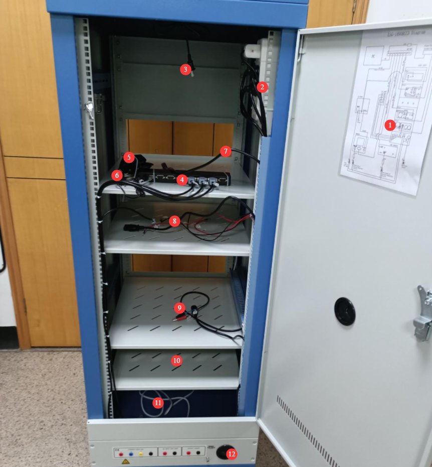
Figura 3-1
3.12 Installazione dell'RT-200C
Per ora, tutto ciò che devi fare è collegarlo alla presa.
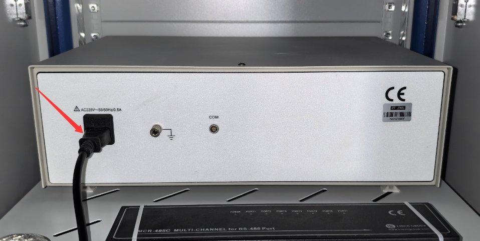
Figura 3-2
3.1.3 Installation of the LS Power Meter
| Numero | Note: |
|---|---|
| ① | Il collegamento avviene tramite un cavo di comunicazione RS-485; l'altra estremità è già collegata alla scatola di comunicazione RS-485 all'interno dell'armadio. |
| ② | Il cavo di alimentazione è collegato; l'altra estremità è già collegata alla ciabatta all'interno del mobile. |
| ③ | Il puntale di prova V1 è collegato al terminale rosso della tensione V del misuratore di potenza. |
| ④ | Puntale di prova V2, collegato al terminale nero della tensione V del misuratore di potenza |
| ⑤ | Puntale di prova A1, collegato al terminale rosso della corrente A del misuratore di potenza |
| ⑥ | Puntale di prova A2, collegato al terminale nero della corrente A del misuratore di potenza |
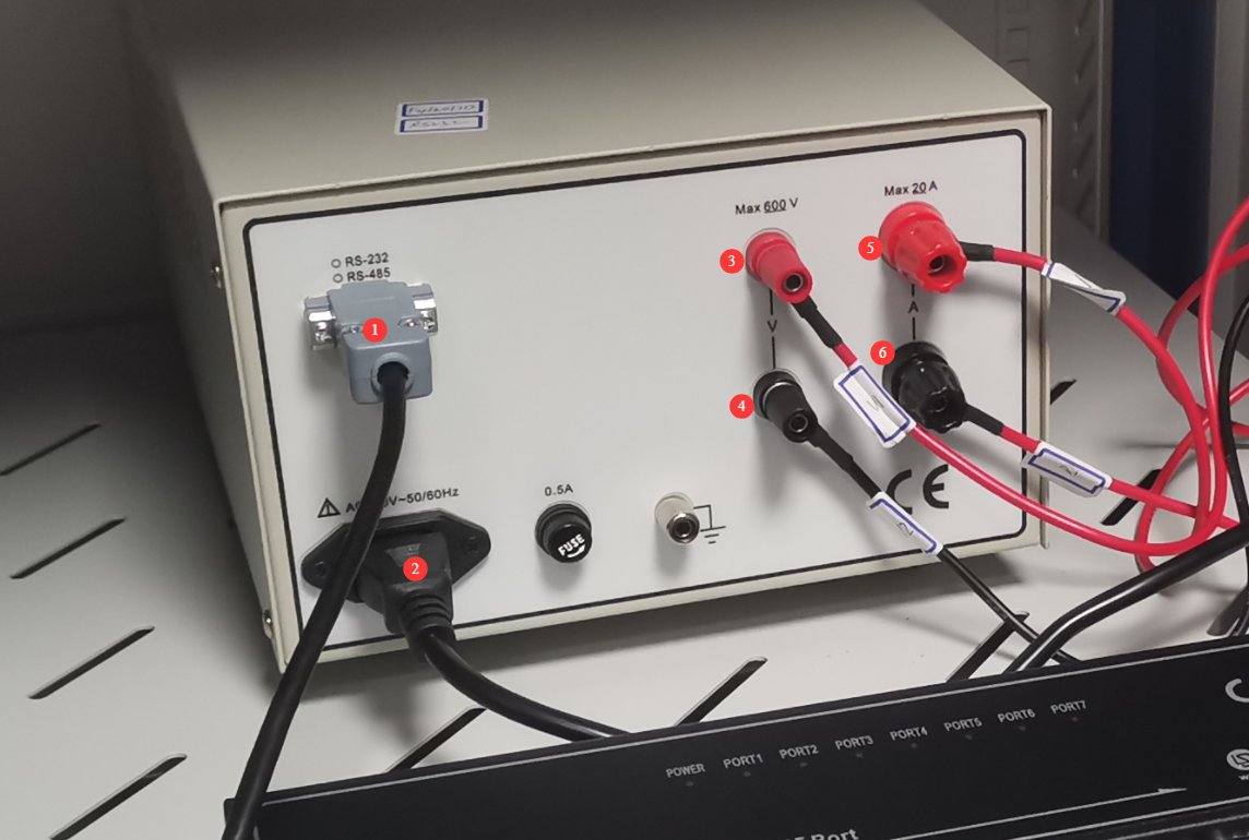
Figura 3-3
3.14 DC Installazione dell'alimentazione elettrica
| Numero | Note: |
|---|---|
| ① | Il collegamento avviene tramite un cavo di comunicazione RS-485; l'altra estremità è già collegata alla scatola di comunicazione RS-485 all'interno dell'armadio. |
| ② | Collegare i fili di uscita dell'alimentazione CC, assicurandosi di far corrispondere i terminali positivo e negativo. |
| ③ | Il cavo di alimentazione è collegato; l'altra estremità è già collegata alla ciabatta all'interno del mobile. |
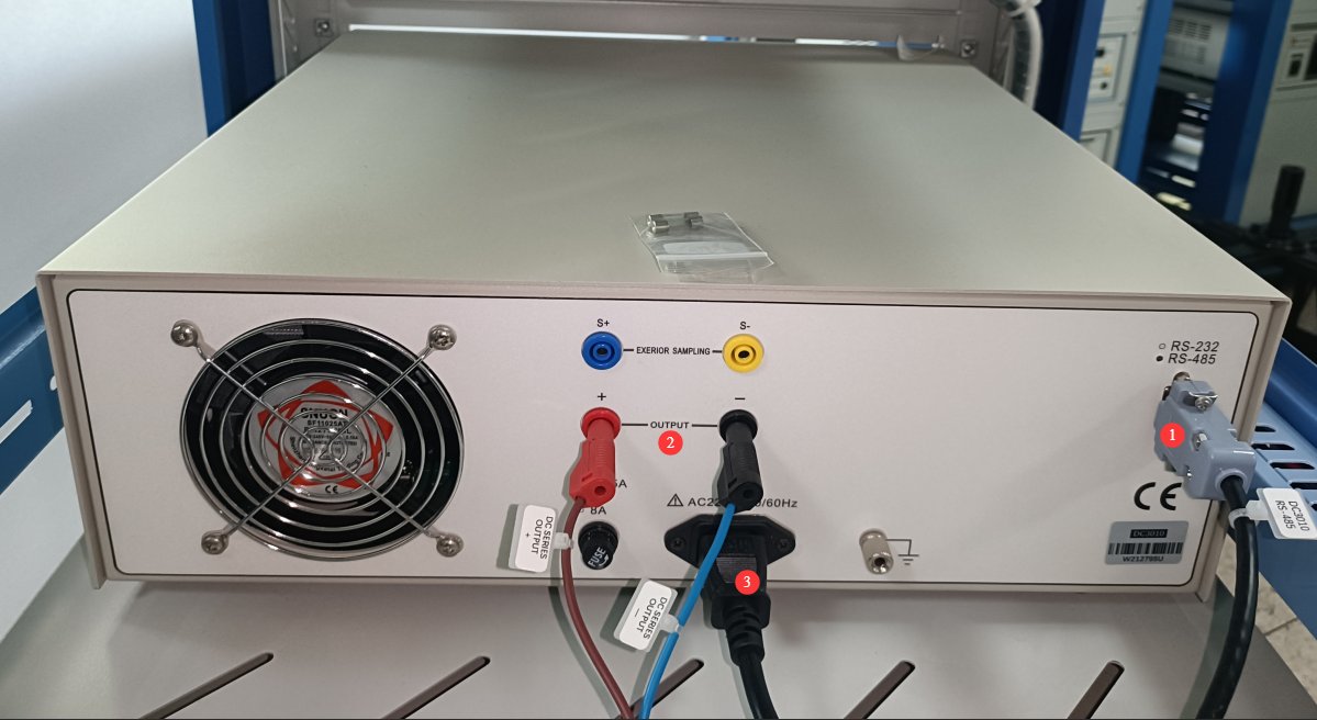
Figura 3-4
3.15 AC Installazione di potenza
Si prega di individuare il seguente cavo di uscita di alimentazione CA tra gli accessori:
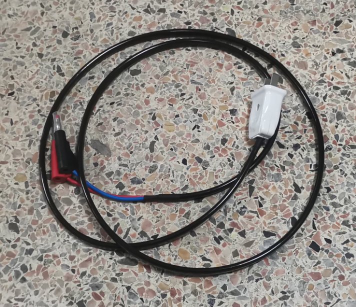
Figura 3-5
| Numero | Note: |
|---|---|
| ① | Il collegamento avviene tramite un cavo di comunicazione RS-485; l'altra estremità è già collegata alla scatola di comunicazione RS-485 all'interno dell'armadio. |
| ② | Il cavo di alimentazione è collegato; l'altra estremità è già collegata alla ciabatta all'interno del mobile. |
| ③ | AC power output cable, routed through the cable opening and ④connected to the location⑤ |
| ④ | Foro del filo |
| ⑤ | AC power output cable, routed through the cable opening and ④connected to the location③ |
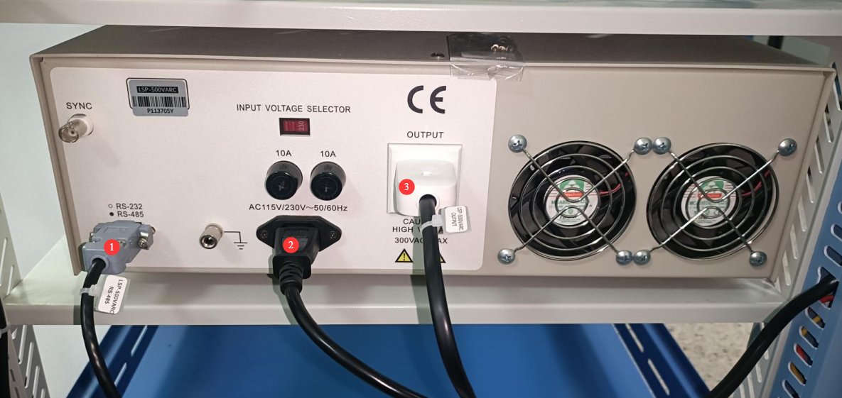
Figura 3-6
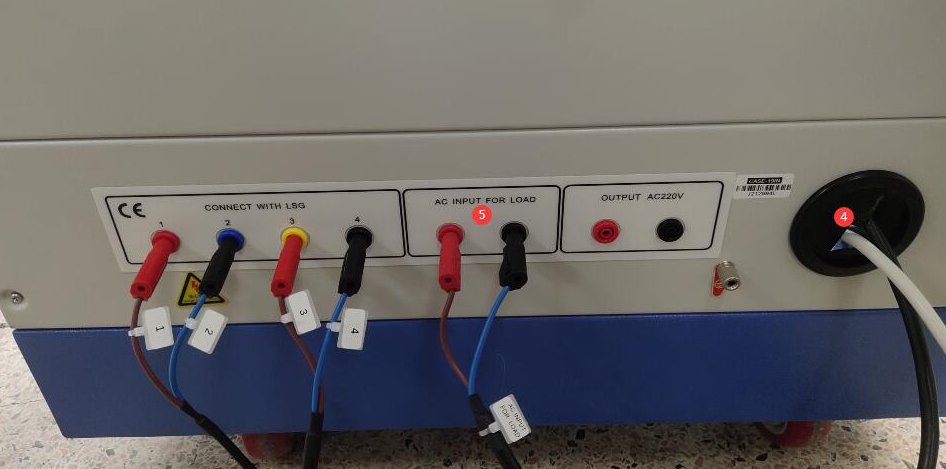
Figura 3-7
3.2 Installation of The Goniophotomoeter Main Unit and Goniophotomoeter Probe
3.2.1 Assemblea ospitante
The same number ②is engraved on both the tapered sleeve of the main unit base and① the corresponding position on the main unit. Rotate the tapered sleeve until the two numbers are aligned, then secure the sleeve using the standard hex screws provided.
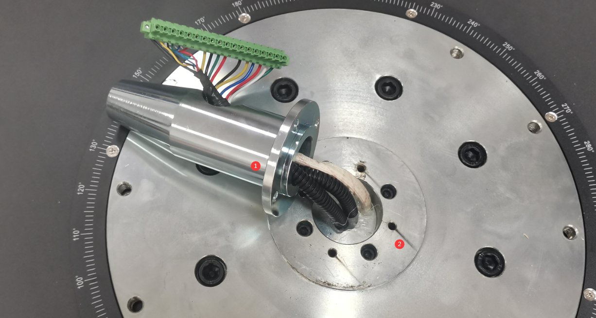
Figura 3-8
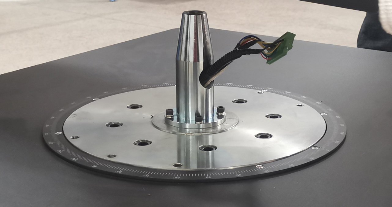
Figura 3-9
Svitare le viti che fissano il coperchio antipolvere al giradischi e rimuovere il coperchio.
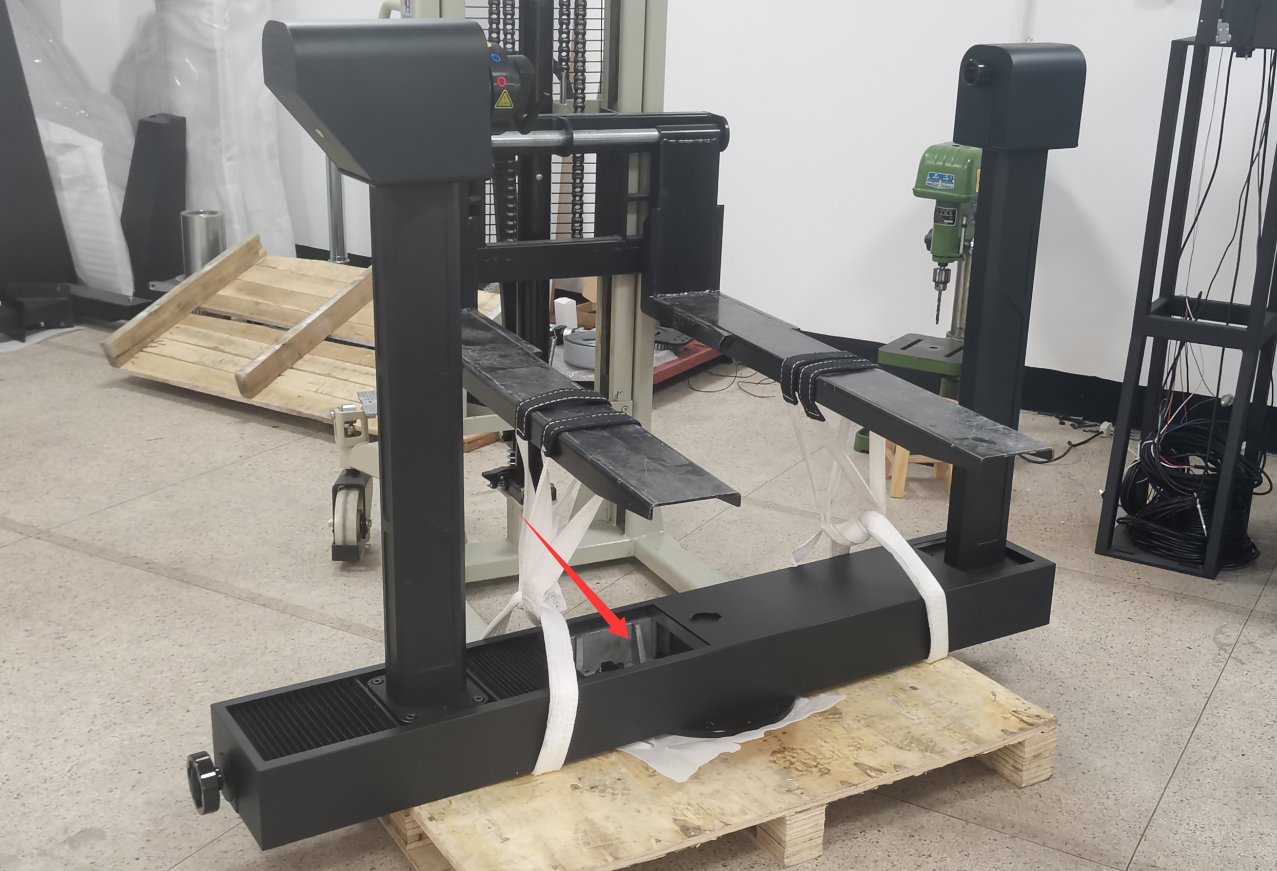
Figura 3-10
Use a forklift to lift the turntable; since the turntable is quite heavy, three to four people can also carefully lift it. Align the dust cover on the turntable with the terminal block on the base, then gently lower the turntable onto the base. Hold the terminal block in place with your hand so that it slides into the turntable along with the tapered sleeve, preventing the terminal block from being crushed by the turntable.
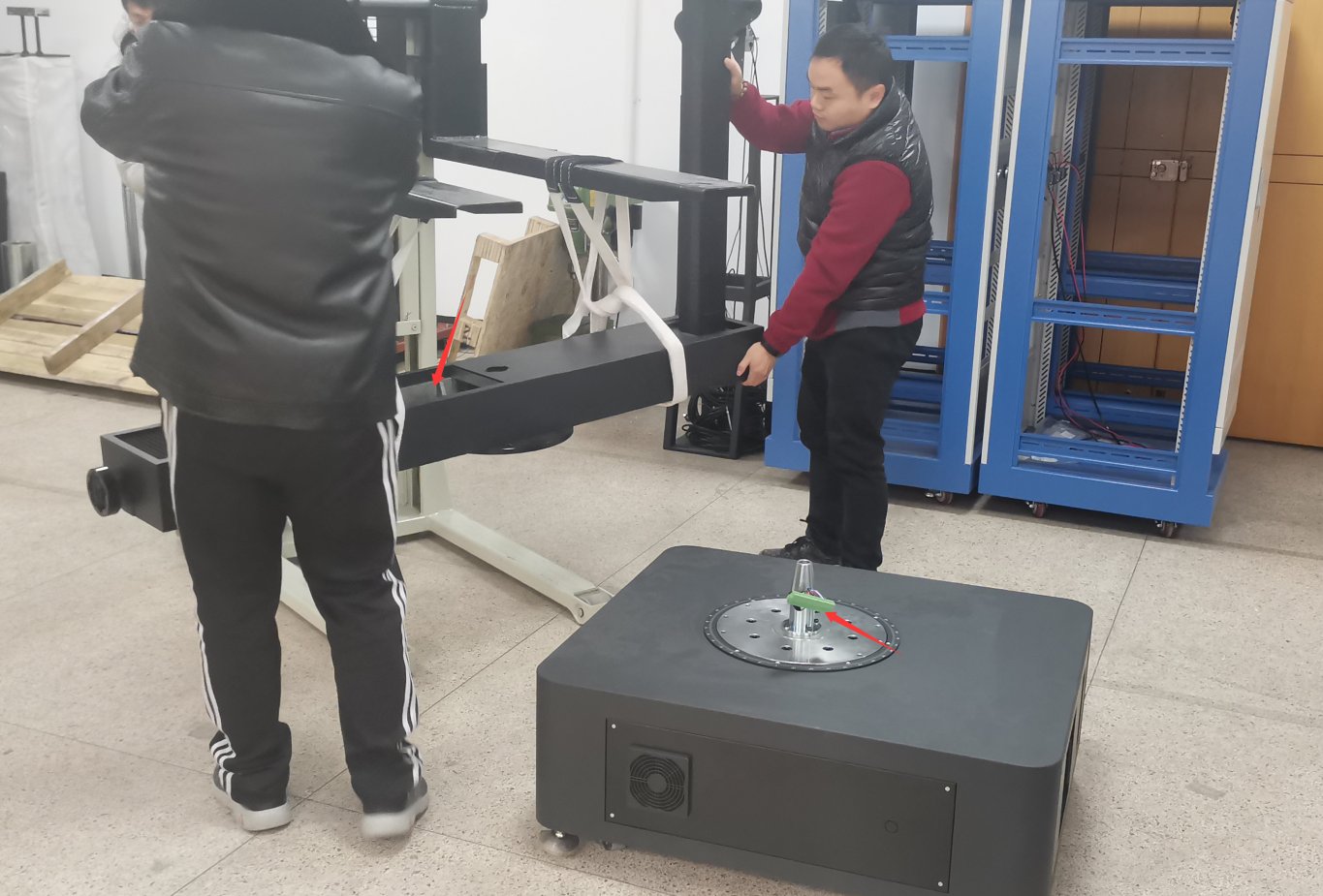
Figura 3-11
To fine-tune the turntable’s orientation, follow these steps in the order listed below.
| Numero | Note: |
|---|---|
| ① | Align the six screw holes on the turntable with the six screw holes on the base, and use the standard hex screws and washers provided to secure the turntable to the base. Note: Be sure to use all the standard washers; otherwise, the screws may not fit properly, which could damage the equipment when the turntable rotates. |
| ② | Collegare la morsettiera di base alla presa della morsettiera corrispondente sul piatto girevole. |
| ③ | Quindi rimetti a posto il coperchio antipolvere. |
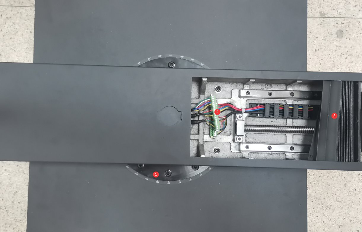
Figura 3-12
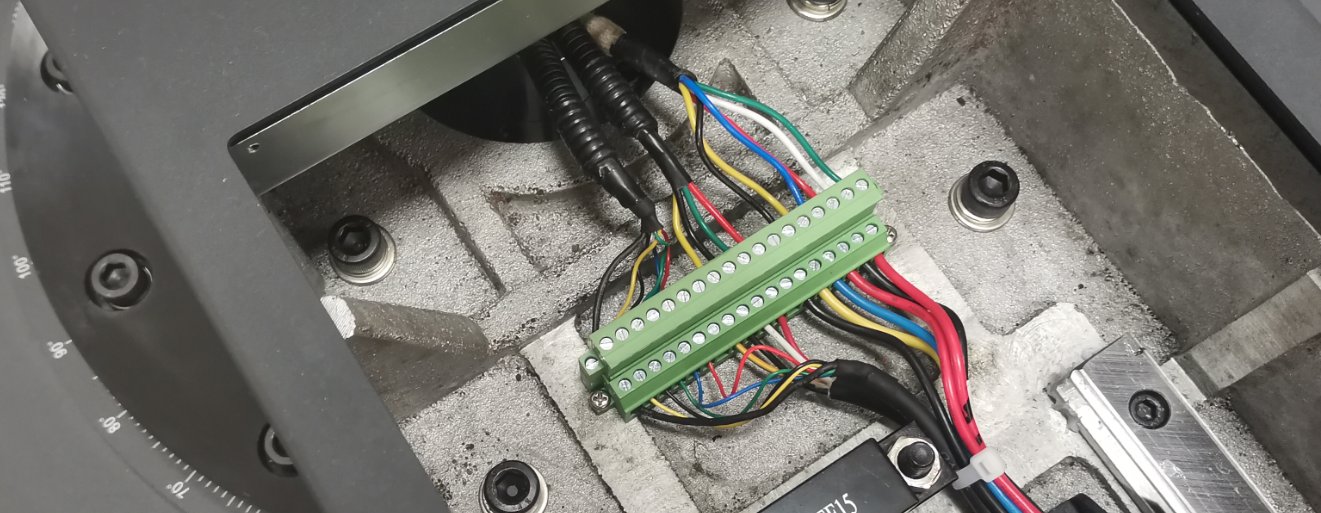
Figura 3-13
I quattro piedini posti alla base dell'unità sono regolabili in altezza.
| Numero | Note: |
|---|---|
| ① | Ruota la vite in basso per sollevare la gamba fino a staccarla da terra. |
| ② | Allo stesso tempo, assicurati che la vite superiore non prema contro nulla; puoi svitarla leggermente. |
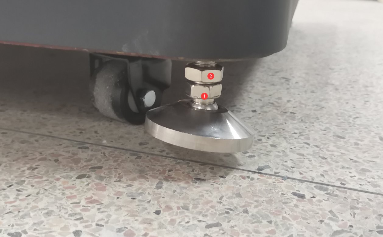
Figura 3-14
Posizionare il goniofotometro nella posizione corretta secondo le planimetrie della camera oscura. Allineare i quattro lati della base il più possibile con le pareti della camera oscura. Quindi rimuovere il braccio ausiliario.
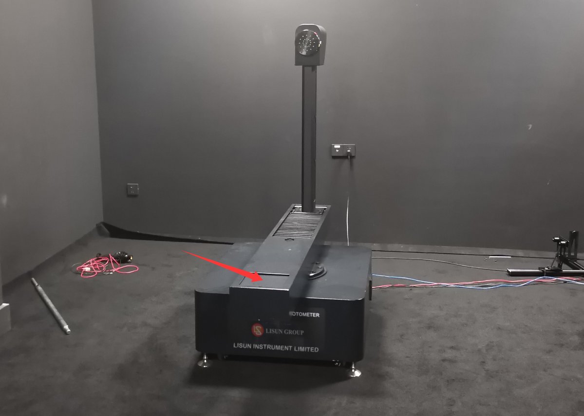
Figura 3-15
Successivamente, ruotare tutte e quattro le gambe del goniofotometro fino a quando non toccano il pavimento.
3.2.2 Assembly of the Photometric Probe and Probe Mount
Prendiamo, ad esempio, una camera oscura con un solo fotometro.
Assemble the photometric probe and probe mount, and position them in the appropriate locations according to the darkroom drawings; there is no need to secure them with screws at this time.
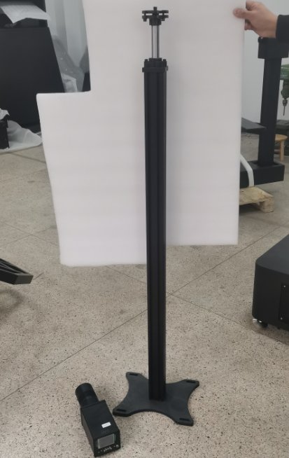
Figura 3-16
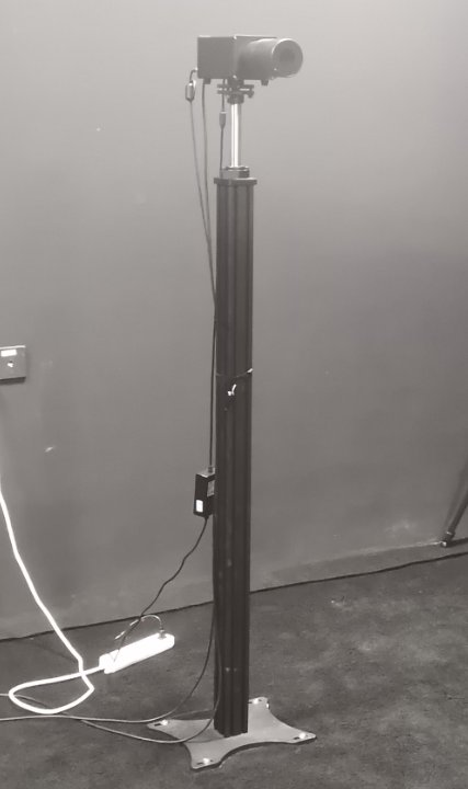
Figura 3-17
3.2.3 Cablaggio del sistema
| Numero | Note: |
|---|---|
| ① | I quattro morsetti ① presenti sul mobile sono collegati al goniofotometro ⑩; è sufficiente abbinarli uno a uno in base ai numeri. |
| ② | The two terminals connect to the terminal block inside the cabinet and are used to supply power to all equipment in the darkroom, including the Goniophotomoeter and photometric probes. This allows for convenient control of all darkroom equipment via the cabinet’s power switch. Note: The darkroom equipment can also be powered directly from the mains. |
| ③ | Terminale di messa a terra del quadro elettrico: collegarlo alla terra tramite un filo. |
| ④ | Cavo di alimentazione del mobile, collegato a una fonte di alimentazione da 220 V, 50/60 Hz. |
| ⑤ | Cavo di alimentazione per l'unità principale del goniofotometro |
| ⑥ | Collega il terminale di terra del goniofotometro alla terra tramite un filo. |
| ⑦ | This is a one-to-two communication cable; one end of the RS-485 cable connects to the RS-485 communication box inside the cabinet, and the other end connects to the rear⑭ of the RT-200C. |
| ⑧ | Photometer probe trigger wire; connects to the probe⑬. When only one probe is installed, the default setting is near-field (N). |
| ⑨ | Generally, if there is only one photometric probe in the anechoic chamber, the far field (F) does not need to be connected. |
| ⑩ | I quattro morsetti ⑩ del goniofotometro sono collegati al quadro elettrico ①; è sufficiente abbinarli uno a uno in base ai numeri. |
| ⑪ | Adattatore di alimentazione per sonda fotometrica |
| ⑫ | Cavo di comunicazione RS-485 per la sonda fotometrica; l'altra estremità si collega alla scatola di comunicazione RS-485 all'interno dell'armadio. |
| ⑬ | Cavo di attivazione della sonda fotometrica, collegato all'unità principale ⑧ del goniofotometro |
| ⑭ | Cavo di comunicazione RT-200C, con l'altra estremità collegata all'unità principale⑦ del goniofotometro |
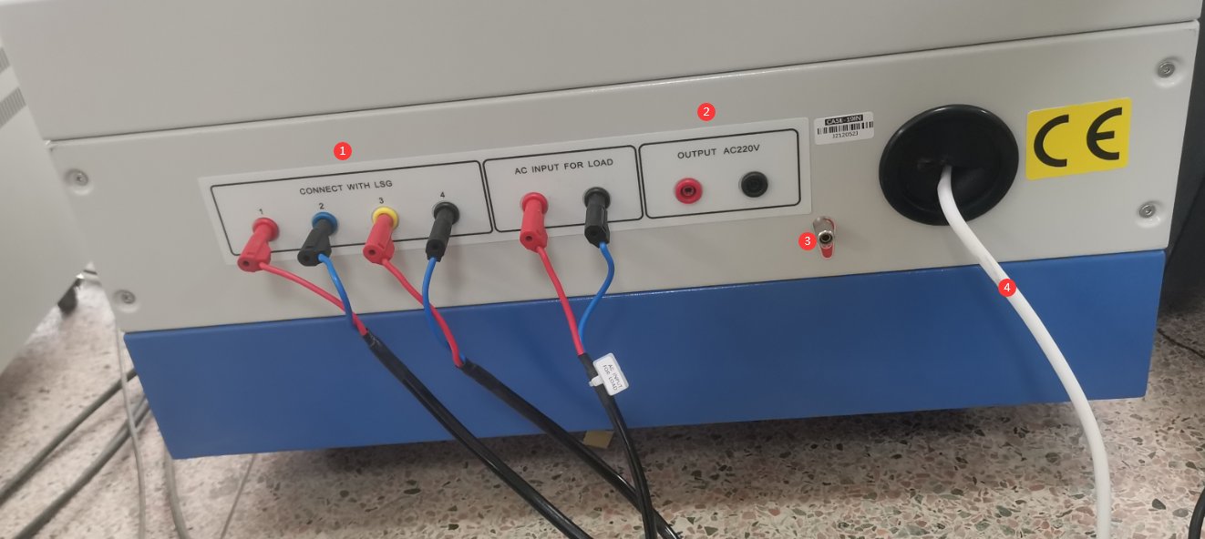
Figura 3-18
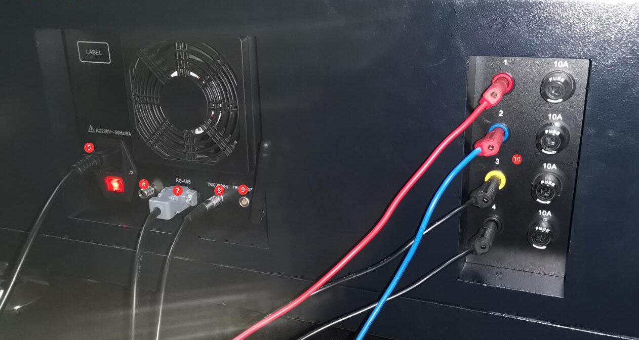
Figura 3-19
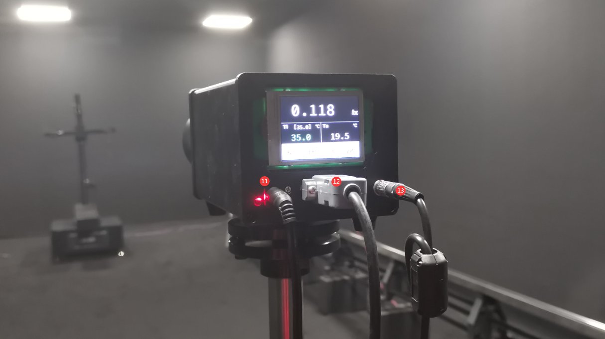
Figura 3-20
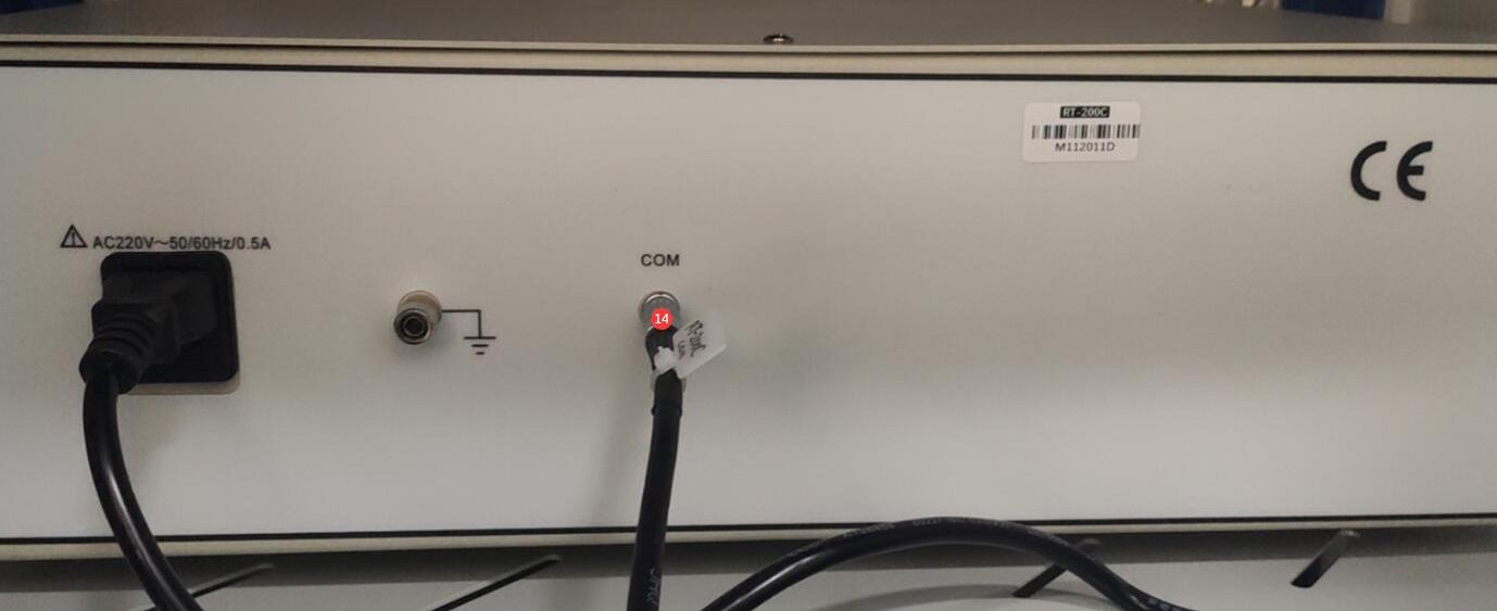
Figura 3-21
4. Installazione e configurazione del software
4.1 Installazione di software e driver
4.1.1 Ambiente di runtime del software
System Requirements: Windows 7/Windows 8/Windows 10/Windows 11 (32-bit/64-bit); the computer must have at least one USB port.
Installazione 4.1.2
| Numero | Note: |
|---|---|
| ① | Software per goniofotometro serie LSG: fare doppio clic per installarlo. |
| ② | Questo file APK può essere copiato su un telefono Android per l'installazione. L'app è destinata esclusivamente alla rotazione del goniofotometro e non può essere utilizzata per scopi di test. Poiché il software include tutte le funzionalità dell'app, questo manuale utilizza il software come esempio di funzionamento. |
| ③ | Driver per box di comunicazione RS485: fai doppio clic per installare. |
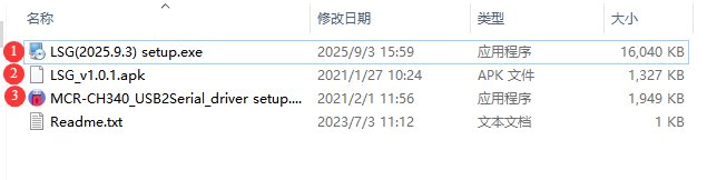
Figura 4-1
4.1.3 Gestione delle eccezioni
Se il software antivirus o il Firewall di Windows segnalano un file come sospetto durante il processo di installazione del software, disattivate temporaneamente il software antivirus o il Firewall di Windows e provate a installare nuovamente il software.
If the software fails to open when you double-click the icon after a successful installation, please verify that you are logged in to your computer with an administrator account. If the software still won’t open after logging in with an administrator account, right-click the software icon to open its Properties window. On the Compatibility tab, check the box next to “Run this program as an administrator,” click “Apply,” and then double-click the icon again to open the software.
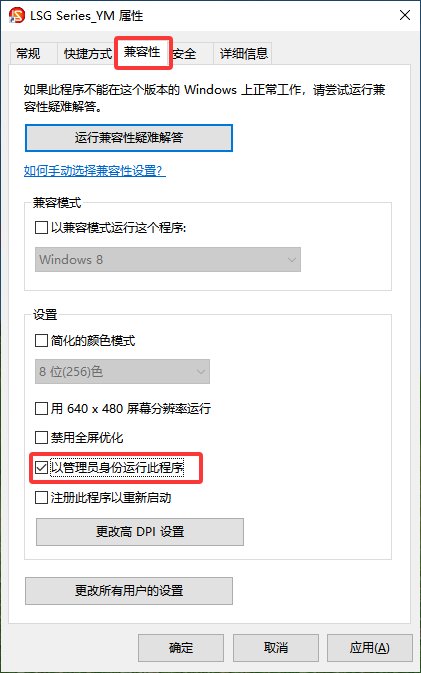
Figura 4-2
4.2 Impostazioni software
First, turn on the cabinet power switch, then power on all system devices, including all equipment inside the cabinet, the Goniophotomoeter unit, and the photometric probes. Double-click to run the software. The first time you run the software, it will automatically open the system configuration screen. Select the correct model for each device you have purchased.
| Numero | Note: |
|---|---|
| ① | Per selezionare un modello di goniofotometro, fai clic sull'elenco a discesa a destra. Il modello che hai acquistato è il LSG-1950S. |
| ② | Sonda fotometrica per campo vicino; selezionare il modello di sonda fotometrica PM400C |
| ③ | Sonda fotometrica a campo lontano: se non ne hai acquistata una, seleziona "Non installata". |
| ④ | Migliori LSG-1950S Non include uno spettro-radiometro di campo vicino; selezionare "Non installato". |
| ⑤ | AC power supply models are generally part of the LSP Series |
| ⑥ | I modelli di alimentatori CC sono generalmente designati come serie CC |
| ⑦ | Modello del misuratore di potenza: Il numero di modello è stampato sul pannello frontale del misuratore di potenza. Si prega di verificarlo e selezionare il modello appropriato. |
| ⑧ | Once you have selected all the correct models, click “Auto-Search Port.” |
| ⑨ | Al termine della ricerca di tutte le porte, fare clic su "OK" per salvare e uscire. |
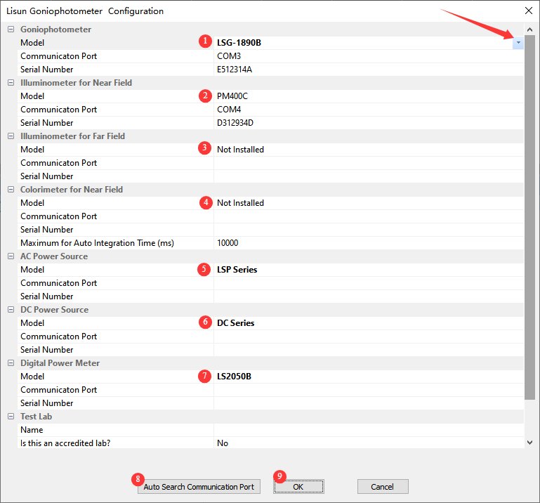
Figura 4-3
Nota: se si verifica un errore di comunicazione durante la ricerca automatica delle porte, leggere attentamente il messaggio di errore, verificare che il dispositivo corrispondente sia acceso e che il cavo di comunicazione RS485 sia collegato correttamente. Dopo aver verificato questi punti, fare nuovamente clic su "Ricerca automatica delle porte" finché non viene stabilita la comunicazione con tutti i dispositivi.
After clicking OK, the software automatically opens the database file save dialog. From then on, all test reports will be automatically saved to this database file.
| Numero | Note: |
|---|---|
| ① | Seleziona il percorso in cui desideri salvare il file del database. Non salvarlo sul desktop o nella cartella Desktop. |
| ② | Inserisci il nome del file |
| ③ | Basta cliccare su “Salva” |
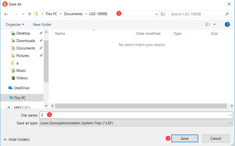
Figura 4-4
5. Calibration of darkroom equipment (Each step must be performed carefully and thoroughly; otherwise, it may result in incorrect calibration data and abnormal test results.)
5.1 Horizontal Commissioning of l'Unità Principale
5.1.1 Predisposto per laser
There is a laser switch on the back of the goniophotomoeter’s main arm. When you turn on the linear laser switch, you will see a red linear laser beam emitted directly in front of the main arm.
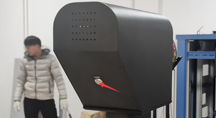
Figura 5-1
Individua il dispositivo laser a croce e il treppiede.
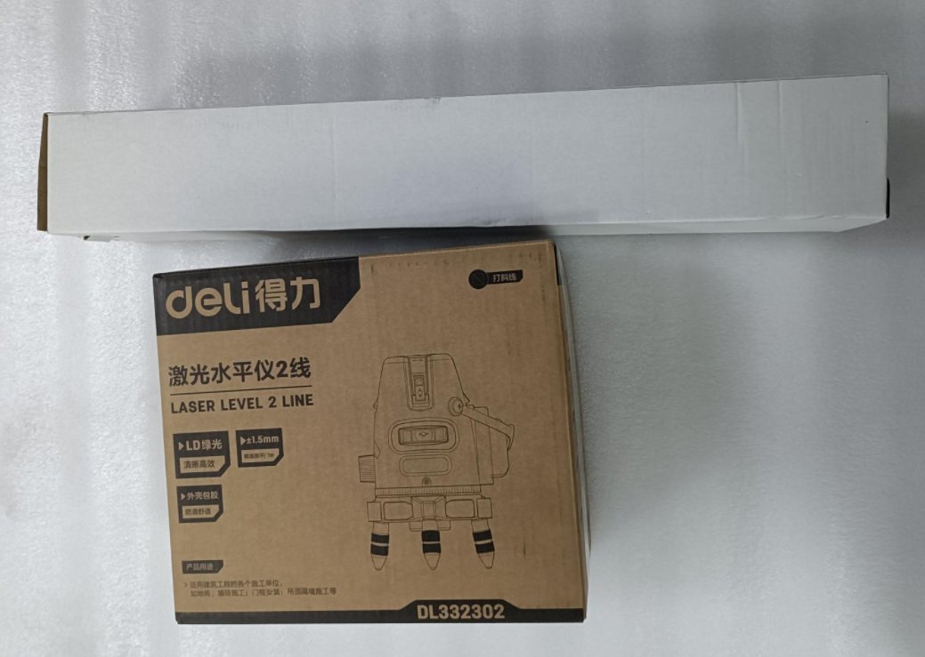
Figura 5-2
Remove the cross-line laser and the batteries. Insert the batteries into the cross-line laser. The power switch is located on the side of the device. Turn the switch to the “Unlock” position to turn on the device.
| Numero | Note: |
|---|---|
| ① | Power switch: Switch to the “unlocked” position to turn on the power. |
| ② | VH si riferisce rispettivamente agli interruttori laser verticali e orizzontali. |
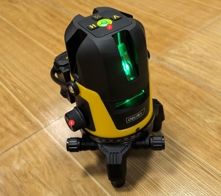
Figura 5-3
Mount the crosshair laser on the tripod.
Note: The cross-line laser is self-leveling. If it is not self-leveled, an audible alarm will sound. This may be due to an uneven surface or an improperly set-up tripod. Please ensure that the cross-line laser remains self-leveled at all times during use.
5.1.2 Steps for Horizontal Commissioning of the Host Machine
Secondo i disegni della camera oscura, l'altezza centrale del LSG-1950S Il goniometro è lungo 1510 mm. Utilizzando un treppiede, regolare l'altezza del raggio laser orizzontale del reticolo laser a 1510 mm. A questa altezza, il raggio laser orizzontale dovrebbe passare attraverso il centro di tutti i fori traslucidi della parete divisoria della camera oscura.
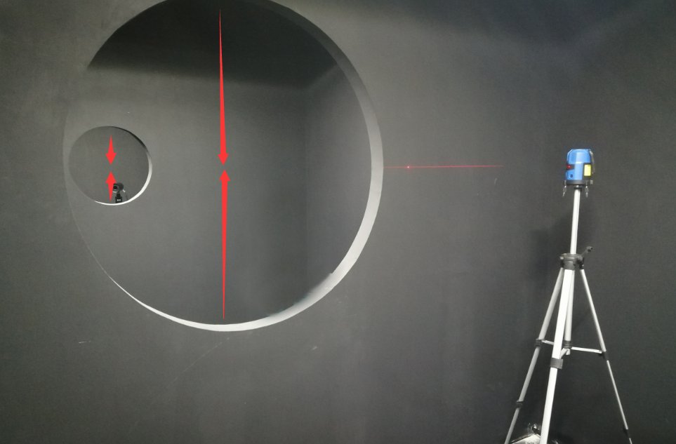
Figura 5-4
Attenzione: non posizionare alcun oggetto sul goniofotometro o nel suo raggio di rotazione per evitare di danneggiare l'apparecchiatura durante la rotazione.
Open the software. Click “Location①” to enter the angle control interface.
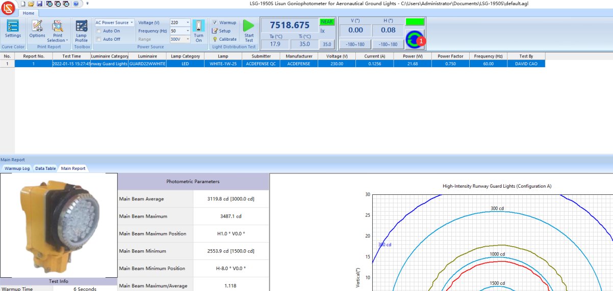
Figura 5-5
To rotate horizontally, ①click the continuous rotation button in any direction. The Goniophotomoeter’s horizontal axis will then begin to rotate continuously. Please make sure not to place any tools or other objects on the Goniophotomoeter’s main unit to avoid damaging the equipment during rotation.
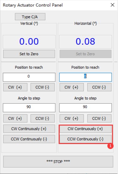
Figure 5–6
A questo punto, osservate i fasci laser orizzontali emessi dai laser a linea singola e a linee incrociate dall'asse principale del goniofotometro.
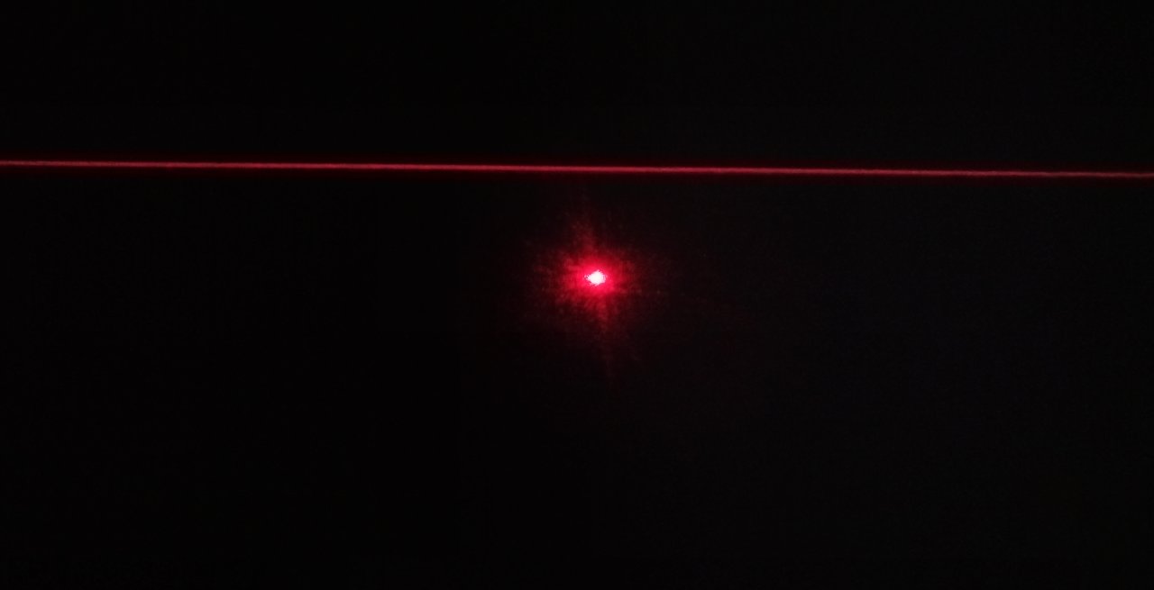
Figura 5-7
Then, using an appropriate wrench, raise the goniophotomoeter and level it by adjusting the height of its four legs. The final result of the calibration: Regardless of the goniophotomoeter’s horizontal rotation angle, its straight laser beam perfectly aligns with the horizontal laser beam, as shown in the figure below.
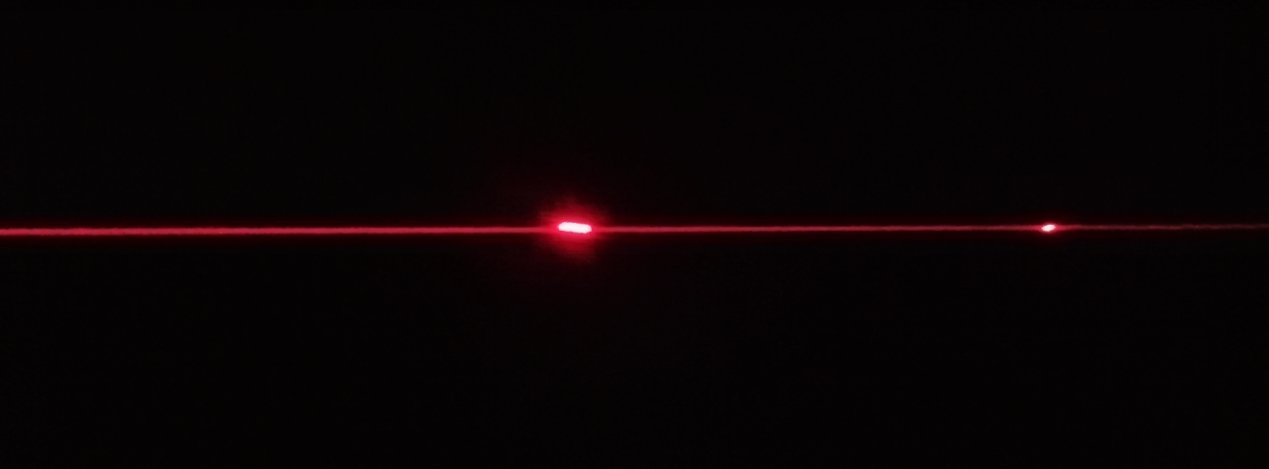
Figura 5-8
You’ll need plenty of patience to complete this step. Once the adjustment is complete, make sure all four legs of the main unit are firmly on the ground. You can then click the “Stop” button on the software’s angle control interface to stop the Goniophotomoeter from rotating. Next, secure the four legs of the Goniophotomoeter by tightening the screws at their tops. Once the Goniophotomoeter’s position and level have been properly adjusted, do not move it again, as doing so will cause the test results to be inaccurate.
5.2 Calibration of the Photometric Probe
5.2.1 Calibration of the Photometric Probe at the 0-Degree Position
| Numero | Note: |
|---|---|
| ① | Immettere 0 |
| ② | Click any rotation direction to rotate the Horizontal axis back to the 0-degree position. |
| ③ | Verify whether the single-line laser is passing through the exact horizontal center of the last aperture at this point. If not, enter a small angle value here based on the actual situation, such as 0.1, etc. |
| ④ | Then click to rotate the Horizontal axis in the correct direction until the single-beam laser level is exactly centered. |
| ⑤ | Click to set the current Horizontal position to 0 degrees; the password is LISUNGRUPPO |
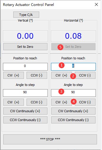
Figura 5-9
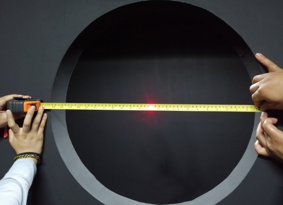
Figura 5-10
Note: After setting the 0-degree mark on the horizontal axis of the photometer probe, do not arbitrarily set another 0-degree mark, as this will cause the test results to be inaccurate.
5.2.2 Mounting the Photometric Probe
Ruotare lo schermo protettivo della sonda luminosa in senso antiorario e rimuoverlo.
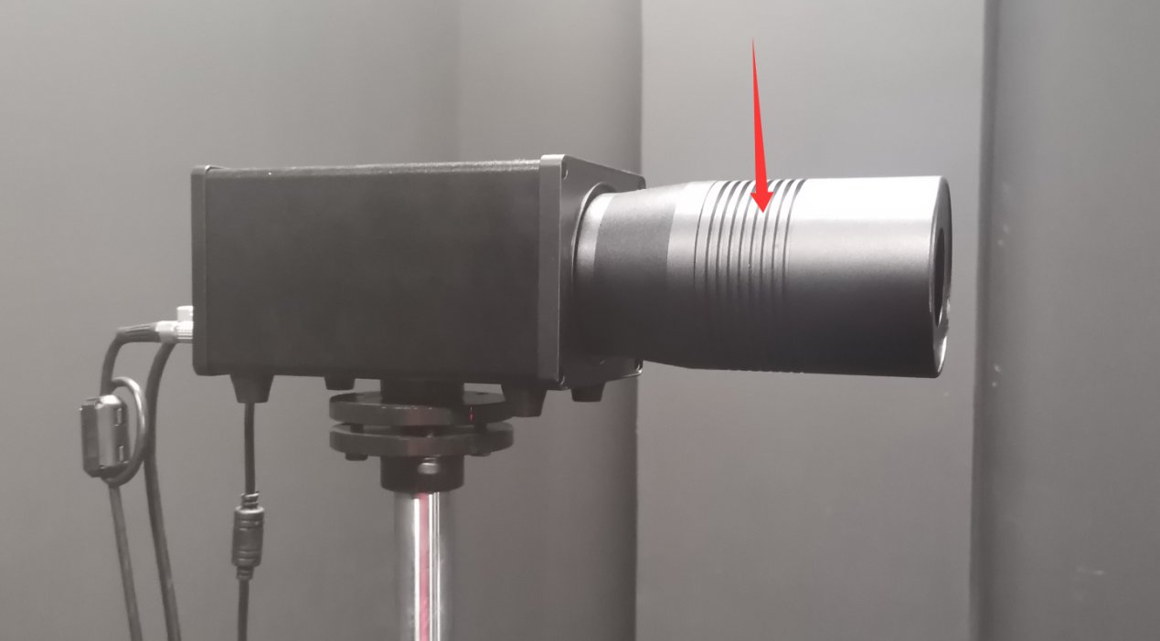
Figura 5-11
La confezione standard della lampada contiene un piccolo specchio.
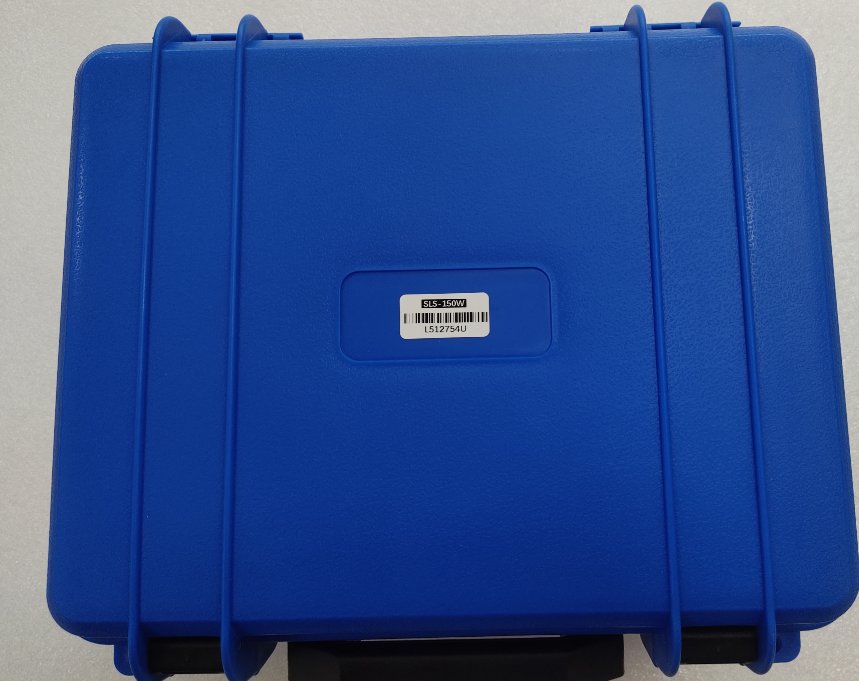
Figura 5-12
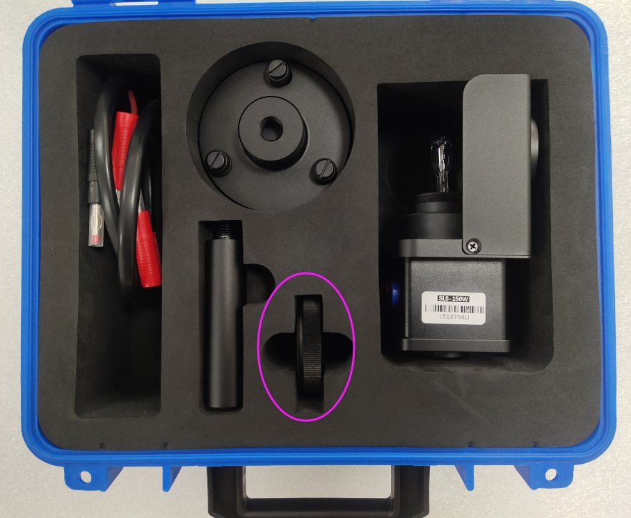
Figura 5-13
Rimuovere il piccolo riflettore e fissarlo alla sonda.
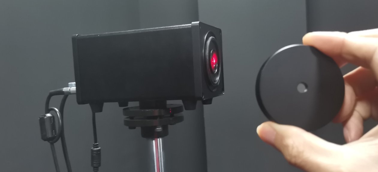
Figura 5-14
At this point, the horizontal axis is still at the 0-degree position. You need to move the probe base slightly and adjust the screws ①at ②points and to adjust the probe’s height and orientation. This ensures that the straight laser beam coming from the spindle hits the exact center of the reflector and that the reflected beam travels back along the same path.
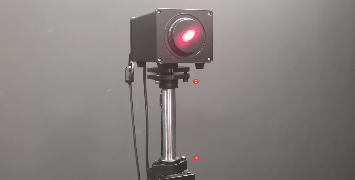
Figura 5-15
Quindi, fissate la base del supporto della sonda al pavimento con delle viti.
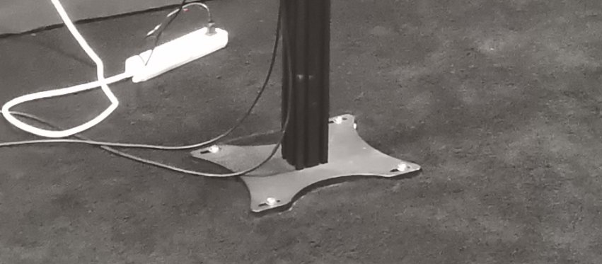
Figura 5-16
Once secured, you may need to make slight adjustments to the probe’s height and orientation so that the straight laser beam continues to hit the exact center of the reflector and the reflected beam travels back along the same path. After calibration is complete, ensure that all screws are tightened. Then remove the reflector and reinstall the light shield on the photometer probe.
Note: Once the probe’s position and orientation have been set, do not change them, as this may cause the test data to be inaccurate.
È possibile fissare l'adattatore di alimentazione della sonda del fotometro alla staffa della sonda, come mostrato nella figura seguente, per proteggere il connettore di alimentazione della sonda.
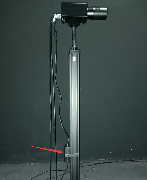
Figura 5-17
5.3 Cross-Line Laser Installation
Infine, il laser a reticolo deve essere montato sulla parete laterale della camera oscura. A seconda della specifica configurazione di ciascuna camera oscura, il laser a reticolo può essere montato sulla parete sinistra o destra. Si prenda come esempio la configurazione della camera oscura mostrata nella figura sottostante.
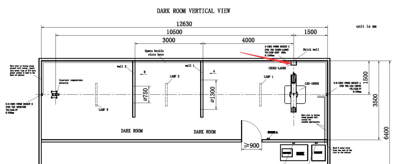
Figura 5-18
Vai alla schermata di controllo dell'angolo.
| Numero | Note: |
|---|---|
| ① | Inserire 90 (se la posizione di installazione del laser a croce nella planimetria della camera oscura è diversa, inserire -90) |
| ② | Click to rotate the horizontal axis to a 90-degree position, so that the main laser beam is directly aligned with the position where the crosshair laser is installed. |
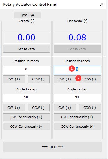
Figura 5-19
Fissare il puntatore laser a croce al supporto triangolare in dotazione.
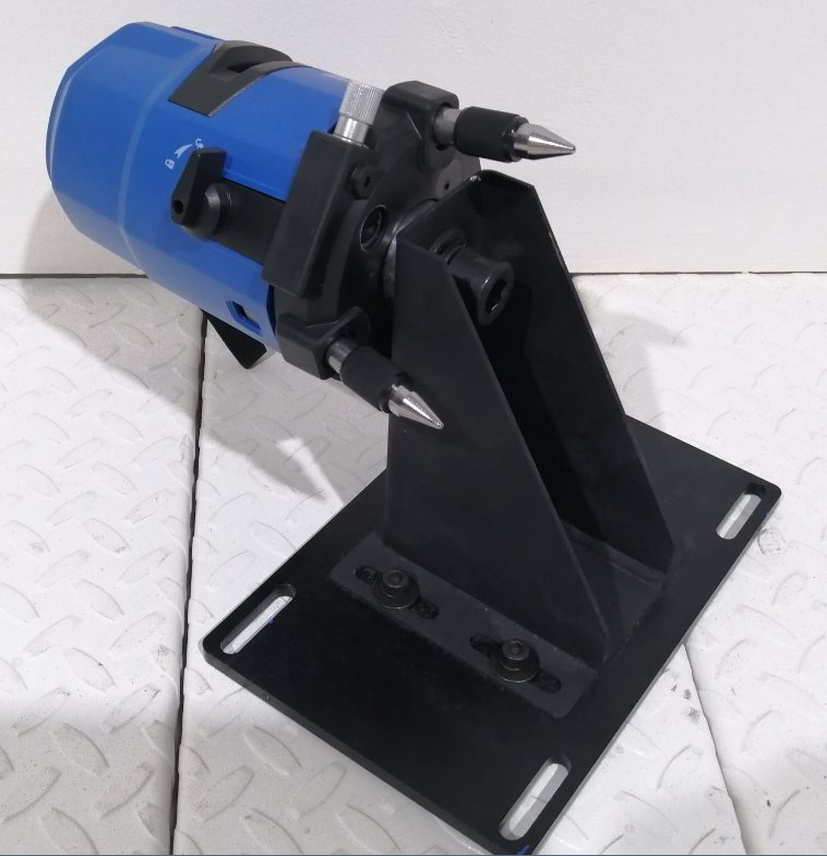
Figura 5-20
Accendete il laser a croce e utilizzate la direzione del laser a linea singola per determinare approssimativamente la posizione del laser a croce.
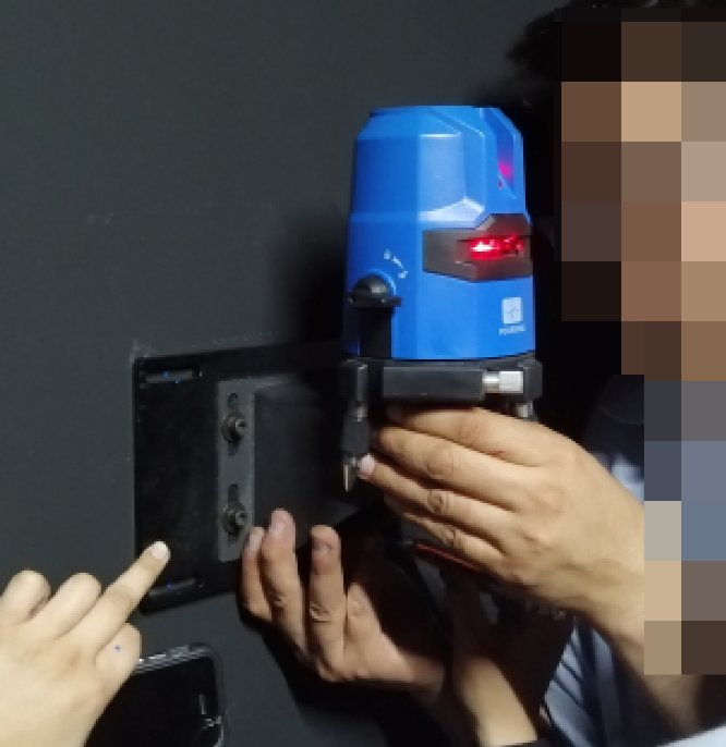
Figura 5-21
Fine-Tune the Position of the Cross-Hairs Laser: The centerline of the horizontal laser should be perfectly aligned with the centerline of the cross-hairs laser. Use the following method to verify and adjust the position. Place a sheet of white paper at the exit of the crosshair laser and at the exit of the single-line laser. If the centerline of the single-line laser coincides with the centerline of the crosshair laser at both locations, you can confirm that the position and orientation of the crosshair laser are correct.
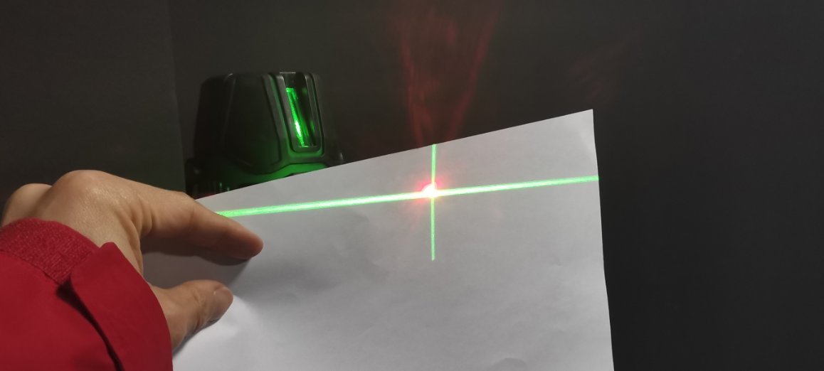
Figura 5-22
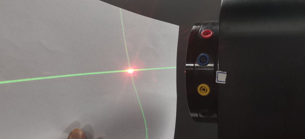
Figura 5-22
Next, secure the cross-laser tripod to the wall using screws. Once secured, if necessary, you can still loosen the screws to make slight adjustments to the cross-laser’s position horizontally and vertically, ensuring it remains correctly aligned. After calibration is complete, all screws should be tightened securely.
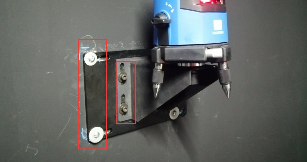
Figura 5-24
Then rotate the horizontal axis back to the 0-degree position. The cross-shaped laser beam is projected onto the opposite wall. You can make a permanent mark. That is, when the cross-shaped laser beam is projected in this direction, it indicates the horizontal and vertical center positions of the Goniophotomoeter. This is required for both calibration and testing.
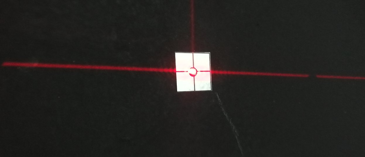
Figura 5-25
Installazione e messa in servizio completate. Spegnere il laser a linea sull'albero principale del goniofotometro.
5.4 Pulizia
È possibile spegnere tutte le apparecchiature. Per farlo, spegnere prima l'interruttore di alimentazione di ciascun dispositivo e poi l'interruttore di alimentazione principale dell'armadio. Successivamente, pulire accuratamente la camera oscura e la sala di controllo. Per evitare che la polvere penetri nelle apparecchiature, coprire i dispositivi con panni antipolvere prima della pulizia. Dopo la pulizia, riaccendere tutte le apparecchiature e continuare con le procedure di calibrazione e collaudo.
Nota: durante l'utilizzo, mantenere la camera oscura il più possibile priva di polvere.
6. Calibrazione
6.1 Installation and Commissioning of Standard Lamps
6.1.1 Installation of the Standard Lamp
Innanzitutto, accendete il puntatore laser a croce sulla parete e ruotatelo per assicurarvi che sia puntato sul segno sulla parete opposta.
Aprire la scatola della lampada standard.
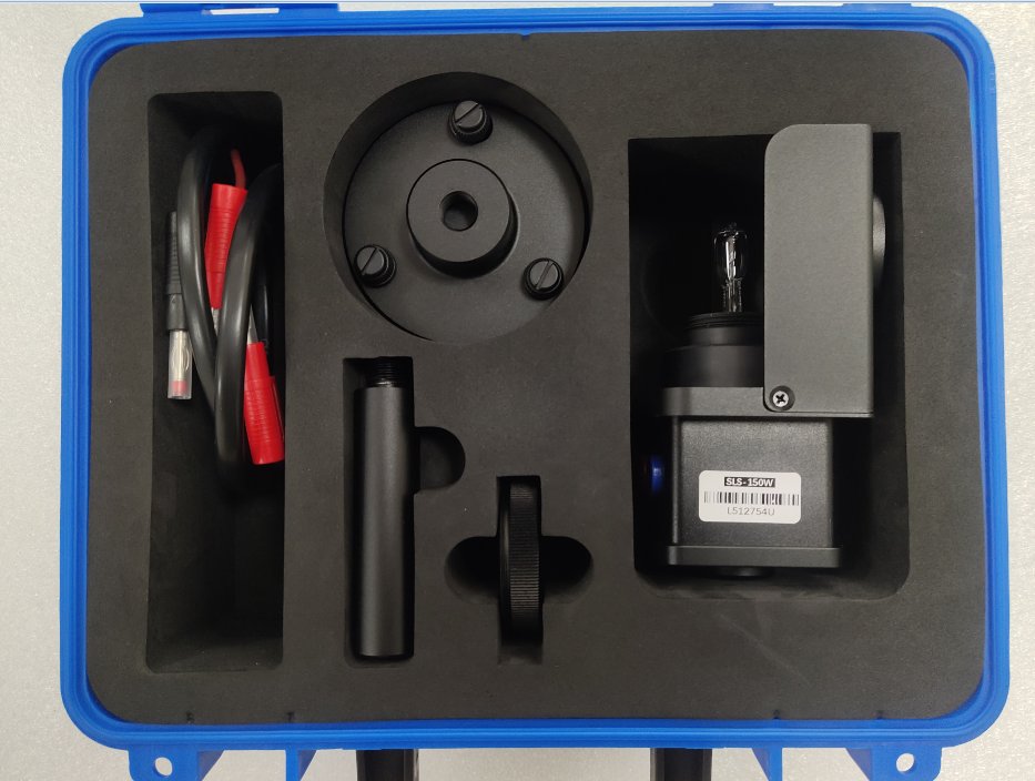
Figura 6-1
Quindi assemblare la staffa della lampada standard come mostrato nella figura sottostante.
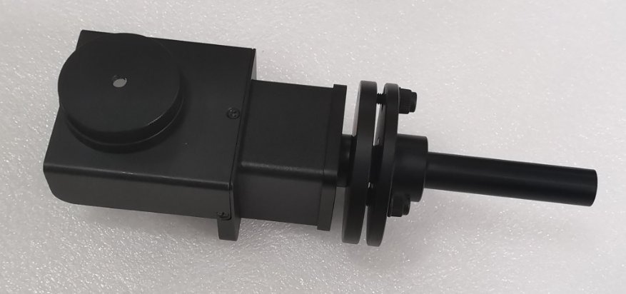
Figura 6-2
The main shaft of the Goniophotomoeter should remain aligned with the photometric probe, i.e., the probe’s 0-degree position. Locate the alignment rod and install it at the center of the Goniophotomoeter. Then remove the top section.
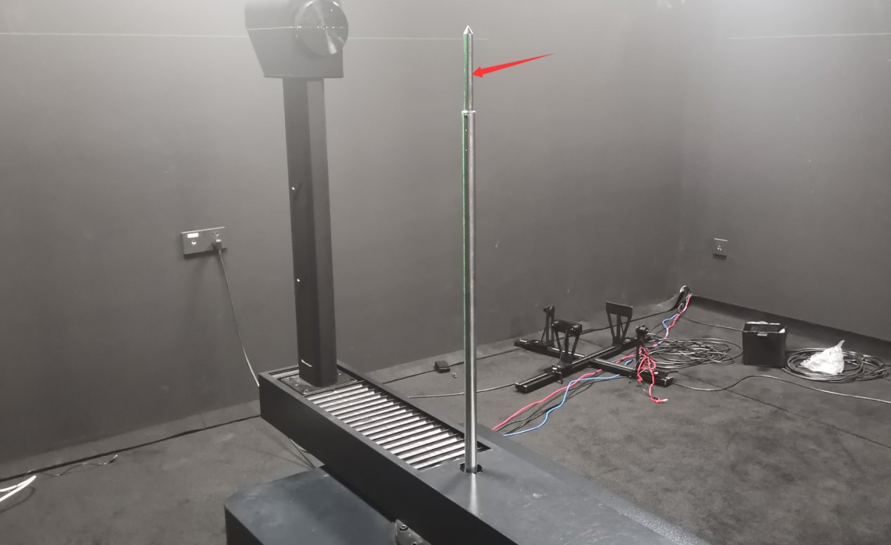
Figura 6-3
Segui le istruzioni riportate di seguito per collegare i fili.
| Numero | Note: |
|---|---|
| ① | The main shaft of the goniophotomoeter has four terminals for connecting the power and sampling cables of the standard lamp and sample luminaire. Use short wires to short-circuit the red and yellow terminals together, and the black and blue terminals together. |
| ② | Connect the power cord of the standard lamp or sample lamp to the red and blue terminals on the main shaft. |
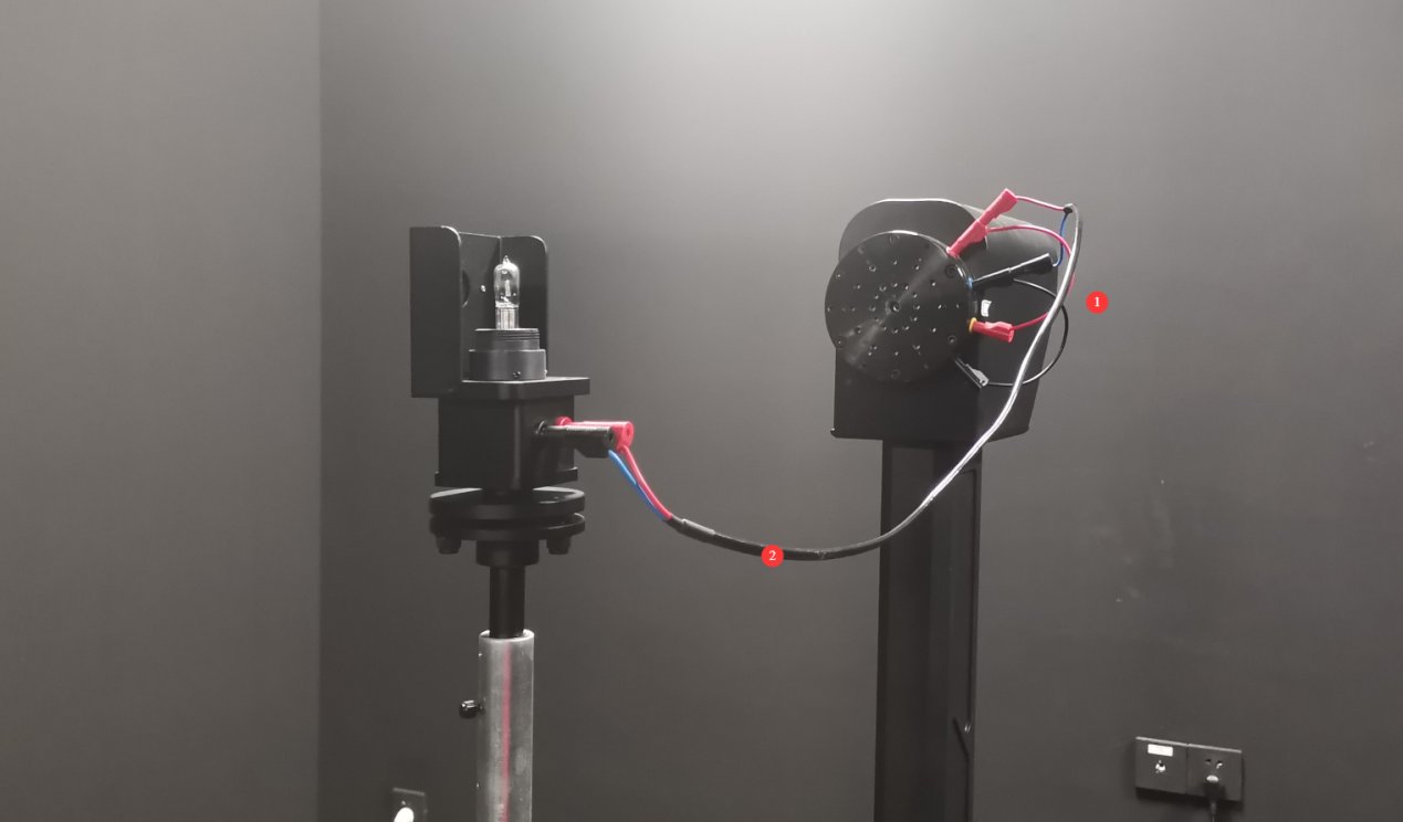
Figura 6-4
6.1.2 Calibrazione della direzione della lampada standard
| Numero | Note: |
|---|---|
| ① | Allenta la vite qui per regolare l'altezza della lampada da terra. |
| ② | Qui sono presenti tre viti che consentono di regolare l'inclinazione del faretto standard. |
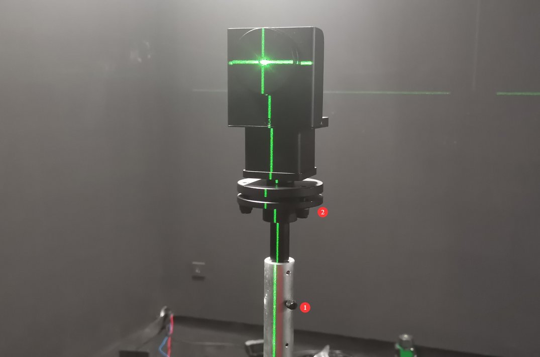
Figura 6-5
The standard lamp should be adjusted so that the cross-shaped laser beam is directed at the center of the small reflector, and the horizontal and vertical laser beams reflected by the reflector coincide exactly with the original cross-shaped laser beam.
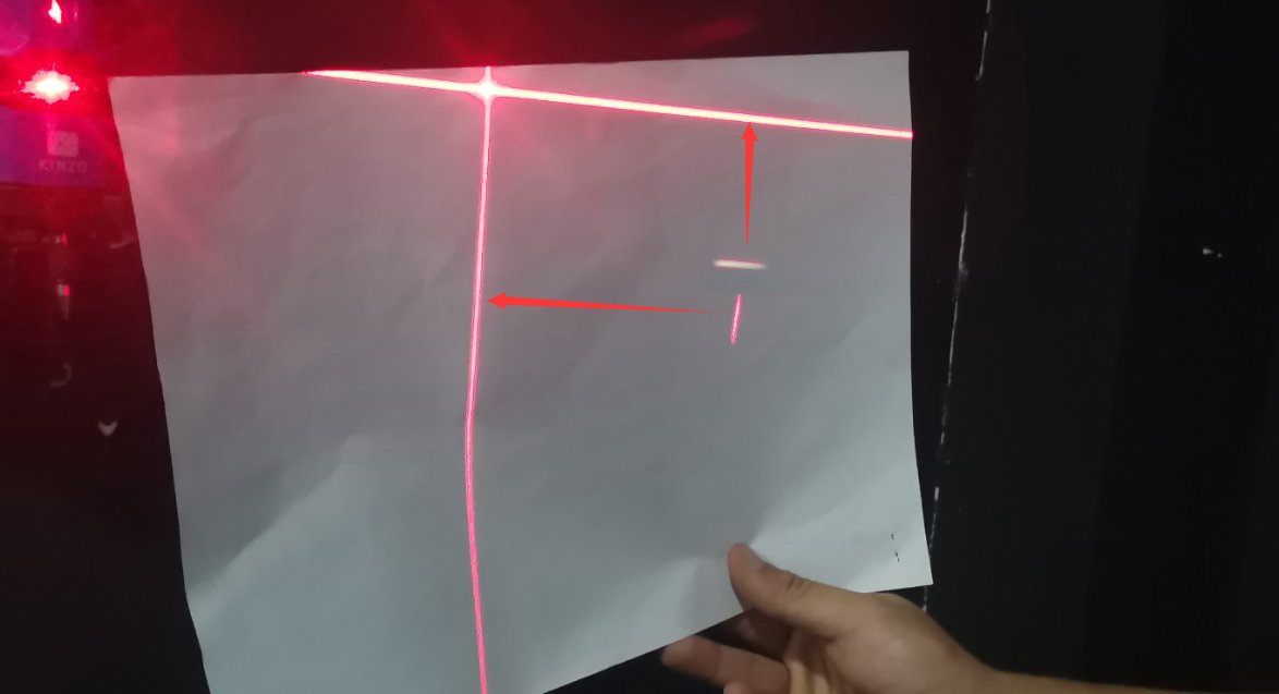
Figura 6-6
Based on our experience, follow these steps for calibration: First, adjust the height of the standard lamp to a suitable position. The vertical reflected laser can be calibrated by rotating the calibration target, while the horizontal reflected laser can be calibrated by adjusting the pitch of the standard lamp. After calibration, the center height of the standard lamp may change, requiring further adjustment of the lamp’s height. Repeat this process until the crosshair laser is projected onto the center of the small reflector, and the reflected horizontal and vertical laser beams perfectly align with the original crosshair laser.
Una volta allineata correttamente la lampada standard, rimuovere con cautela il piccolo riflettore, facendo attenzione a non alterare l'allineamento della lampada standard durante la rimozione. Quindi spegnere il laser del reticolo.
6.2 Calibration of the Photometric Probe
Tutte le lampade standard sono sorgenti luminose a corrente continua (CC). Impostare l'interruttore CA/CC dell'armadio su CC.
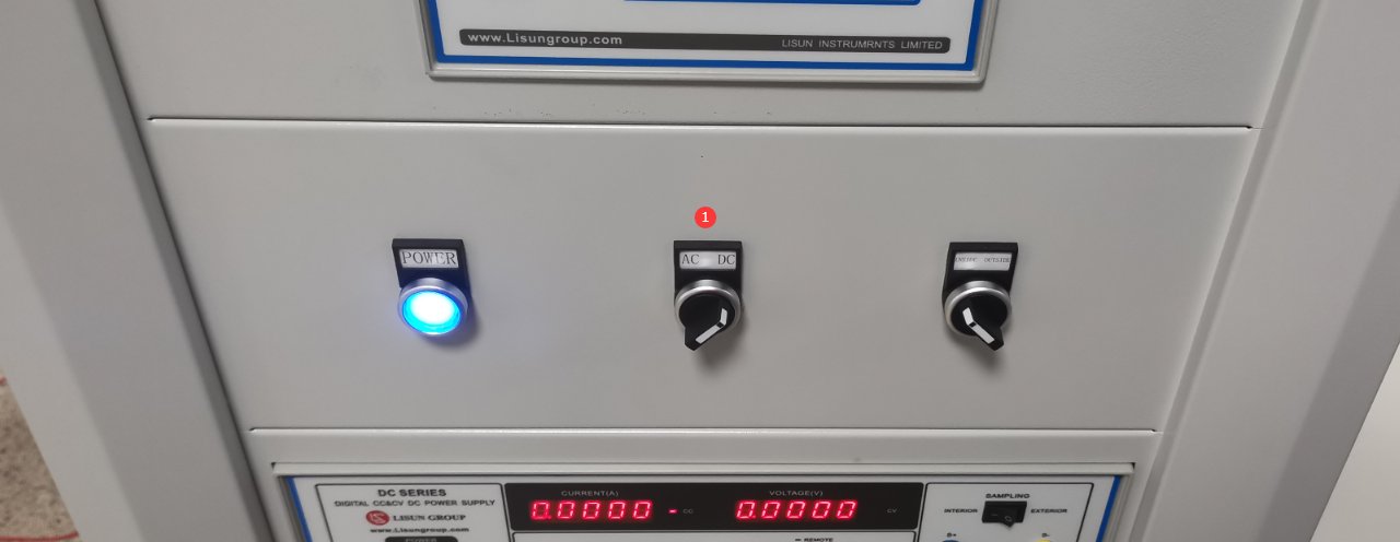
Figure 6–7
Aprire il controller angolare software.
| Numero | Note: |
|---|---|
| ① | Inserisci -90 |
| ② | Click to rotate the horizontal axis to the -90-degree position (if the crosshair laser is installed in a different position on your darkroom blueprint, you’ll need to rotate it to the 90-degree position). Note: To rotate from 0 degrees to -90 degrees, using CCW (counterclockwise) will be faster. |
Figure 6–8
Align the round hole in the standard lamp holder so that it faces the photometric probe.
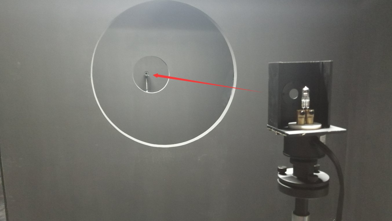
Figure 6–9
Accendere la lampada di calibrazione e accedere all'interfaccia di calibrazione.
| Numero | Note: |
|---|---|
| ① | Selezionare un alimentatore CC |
| ② | La lampada standard è una sorgente luminosa a corrente costante. Selezionare CC (modalità corrente costante) e immettere la tensione di riferimento e la corrente nominale come specificato nel certificato della lampada standard; in genere, questi valori sono 30 V e 6.1 A. |
| ③ | Fai clic per accendere la lampada standard e spegnere tutte le altre luci nella camera oscura. La lampada standard impiega 15 minuti per raggiungere uno stato stazionario. |
| ④ | Una volta stabilizzata la lampada standard, fare clic per accedere all'interfaccia di calibrazione del fotometro. |
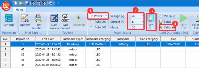
Figura 6-10
Close the darkroom door and make sure all light sources in the darkroom are turned off, except for the standard lamp.
| Numero | Note: |
|---|---|
| ① | Based on the standard lamp certificate, enter the correct luminous intensity value. |
| ② | Fai clic per iniziare |
| ③ | After calibration is successful, the software will automatically calculate the test distance. |
| ④ | Fai clic sull'app |
| ⑤ | If you want to double-check the real-time light intensity data, click “Test.” |
| ⑥ | Under normal circumstances, the real-time light intensity displayed should be very close to the input light intensity value. |
| ⑦ | Then click “Save and Exit.” |
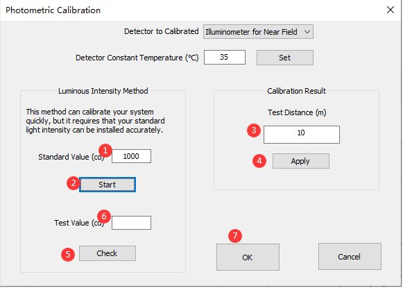
Figura 6-11
Note: The test distance is the distance from the center of the Goniophotomoeter to the surface of the photometric probe. The distance calculated by the software should be close to the actual distance; an error of 1% or less is considered normal. If the error is too large, please refer to Section 2.3.1 to verify that the darkroom is functioning properly, and refer to Chapter 5 to verify the calibration steps.
Una volta completata la calibrazione, è possibile spegnere la lampada standard tramite il software. Poiché la lampada standard si surriscalda notevolmente durante l'uso, attendere che si raffreddi prima di riporla nella sua confezione per una conservazione sicura. Rimuovere l'asta di calibrazione e conservarla in un luogo sicuro.
6.3 Taratura e manutenzione
| Nessun cambiamento in camera oscura | Se non sono state apportate modifiche al computer, la ricalibrazione non è necessaria. |
| Non è stata apportata alcuna modifica al computer; è sufficiente scollegare e ricollegare il cavo di comunicazione o reinstallare il software Goniophotomoeter. Non è necessaria alcuna ricalibrazione. | |
| If you switch computers or reinstall the operating system, there is no need to recalibrate; simply enter the previous test distance and save it. | |
| Cambiamenti in camera oscura | The structure of the darkroom remains unchanged; however, after prolonged use, the interior paint may fade or peel. Depending on how well you maintain the darkroom and the level of accuracy you require for your test results, you may want to repaint the darkroom periodically. After repainting, the darkroom must be recalibrated. |
| A seguito di una modifica nella configurazione della camera oscura, è necessaria una ricalibrazione. |
7. Preparations Before Testing
7.1 Lamp Selection and Aging
Selezionare apparecchi di illuminazione rappresentativi per i test, conformi agli standard nazionali o aziendali; i nuovi apparecchi di illuminazione devono essere sottoposti a un trattamento di invecchiamento (per gli apparecchi a LED, si raccomanda un periodo di invecchiamento di 24 ore);
Verificate che l'apparecchio di illuminazione non presenti danni visibili, che il cablaggio interno sia collegato correttamente e pulite eventuali macchie dalla superficie dell'apparecchio.
7.2 Introduction to Test Mode
A-Alpha Mode: Suitable for automotive lights, traffic signals, etc.
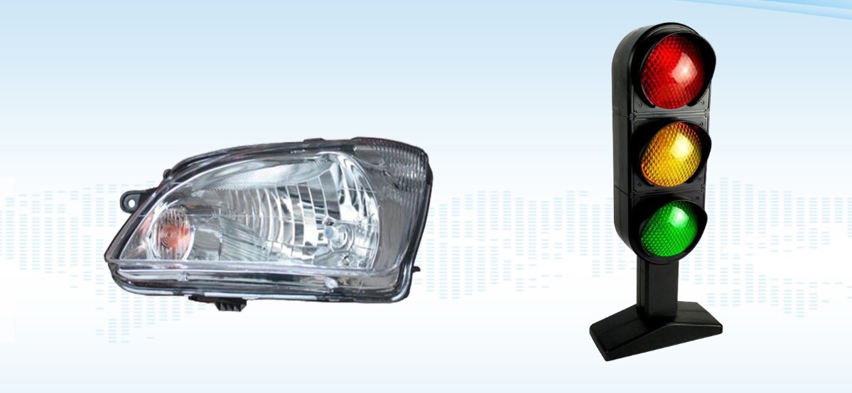
Figura 7-1
B-Beta Mode: Suitable for floodlights, spotlights, and similar fixtures.
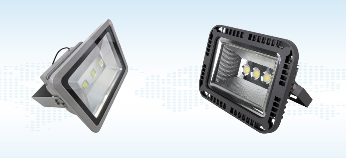
Figura 7-2
Modalità C-Gamma: Adatta alla maggior parte degli apparecchi di illuminazione, come lampioni, faretti, pannelli luminosi e lampade per la coltivazione di piante.
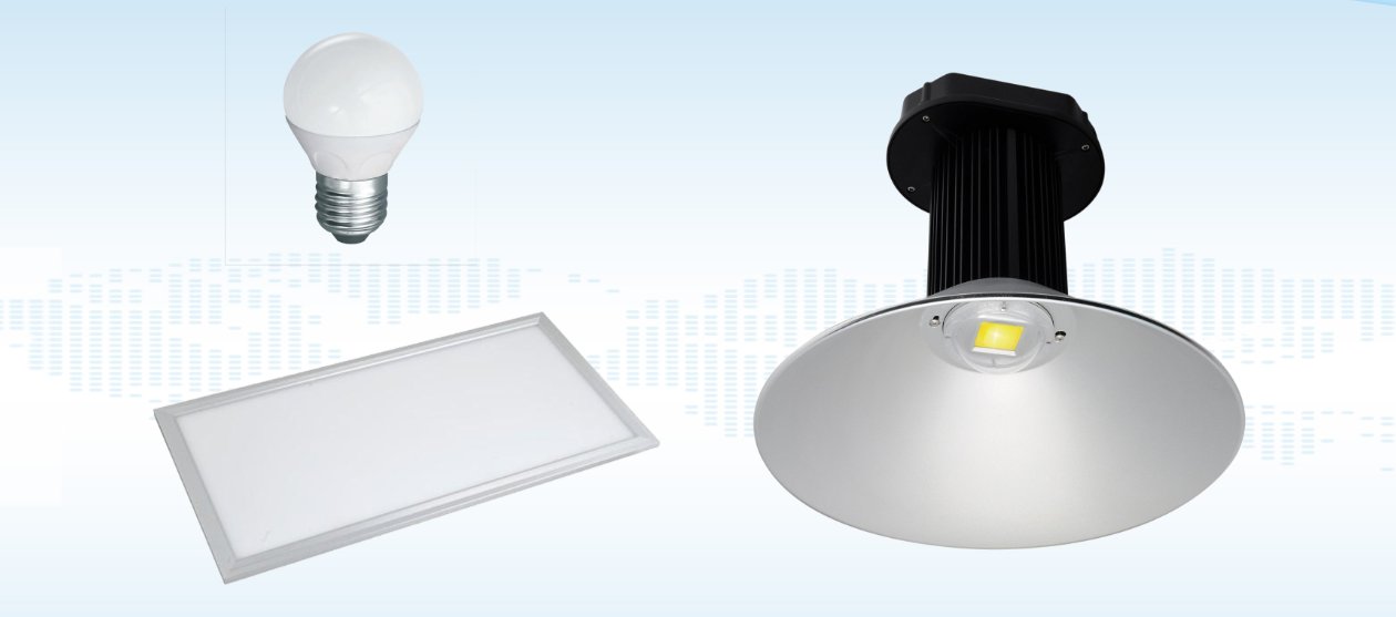
Figura 7-3
Nota: Il LSG-1950S is specifically designed for A-Alpha testing. If you need to perform B-Beta or C-Gamma testing, please contact us.
8. High-beam and signal light intensity and distribution test
8.1 Installing and Turning On the Lights
8.1.1 Installazione dell'apparecchio di illuminazione
Install the fixture and the sample as shown in the figure. Use the cross-hair laser on the wall to ensure the sample is positioned exactly in the center.① Connect the sample’s power cord to the main unit.
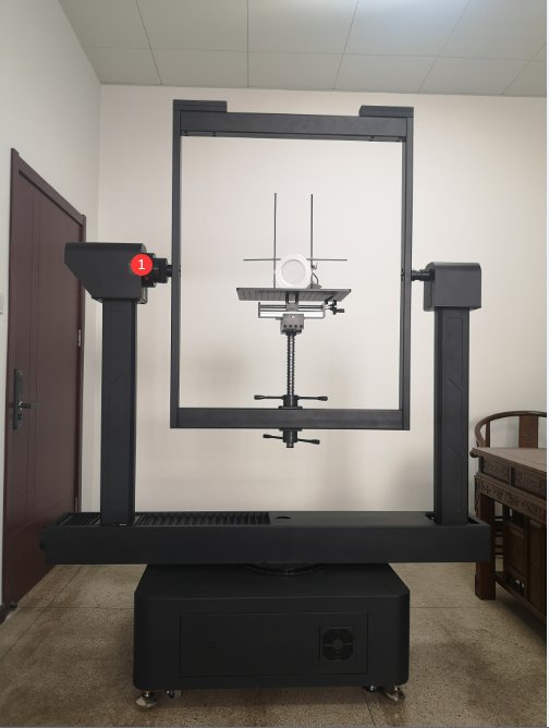
Figura 8-1
Note: When the Horizontal angle is rotated to the 90-degree position, the light-emitting surface of the sample should face directly toward the probe. After the
sample is in place, close the darkroom door and turn off all other lights in the darkroom.
8.1.2 Accensione delle luci
Regolare l'interruttore del mobile in base ai parametri dell'apparecchio di illuminazione in fase di prova.
| Numero | Note: |
|---|---|
| ① | If the sample luminaire is powered by AC, switch to the AC side; if it is powered by DC, switch to the DC side. |
| ② | Interruttore di campionamento interno/esterno per parametri elettrici. Il campionamento esterno utilizza una configurazione a quattro fili e fornisce letture di tensione più precise. Salvo diversa indicazione, impostare questo interruttore su "Campionamento esterno"; non sono necessarie ulteriori regolazioni. |
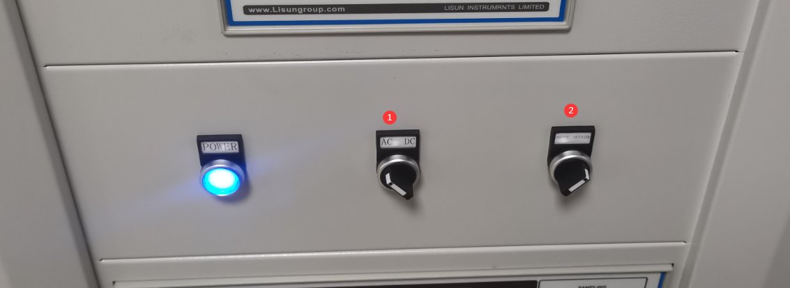
Figura 8-2
Se l'apparecchio di illuminazione campione è alimentato a corrente alternata.
| Numero | Note: |
|---|---|
| ① | Selezionare l'alimentazione CA |
| ② | In base ai parametri del campione, immettere la tensione e la frequenza corrette. |
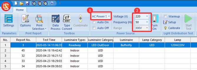
Figura 8-3
If the sample luminaire is powered by DC.
| Numero | Note: |
|---|---|
| ① | Selezionare un alimentatore CC |
| ② | In base ai parametri del campione, immettere la tensione e la corrente corrette. |
| ③ | Select the output mode: CC stands for constant current, and CV stands for constant voltage. If you select constant current, you need to enter the sample’s rated current value; for the voltage, simply enter the maximum output voltage of this DC power supply. If you select constant voltage, enter the sample’s rated voltage and the DC power supply’s maximum output current. Note: If your DC power supply model is DC3010La sua tensione di uscita massima è di 30 V e la sua corrente di uscita massima è di 10 A. |
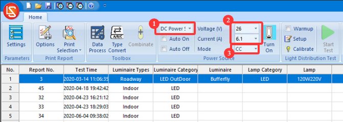
Figura 8-4
The software offers two methods for turning the sample lamp on and off, and users can choose between them as they wish.
| Numero | Note: |
|---|---|
| ① | Selezionando le opzioni "Accensione automatica" e "Spegnimento automatico", il software accenderà automaticamente il campione utilizzando la fonte di alimentazione selezionata e i parametri elettrici inseriti all'inizio del test, e lo spegnerà automaticamente al termine del test. |
| ② | If the “Auto On” and “Auto Off” options are not checked, you can also click this button; the software will power on the sample based on the selected power source and the entered electrical parameters. Clicking this button again will turn off the sample’s power. |
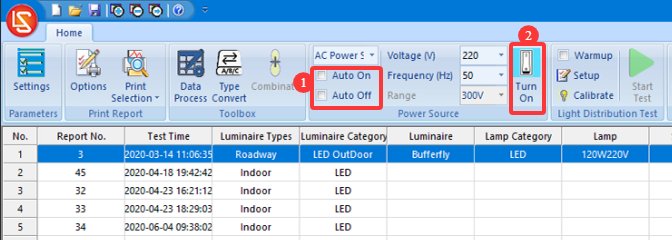
Figura 8-5
8.2 Impostazioni dei parametri di preriscaldamento
| Numero | Note: |
|---|---|
| ① | If you check the “Preheat” box, the software will preheat the luminaire according to the specified preheat parameters when the test begins, and the test will start automatically once preheating is complete. If you do not check the “Preheat” box, the software will begin the test immediately. |
| ② | Impostazioni dei parametri di preriscaldamento |
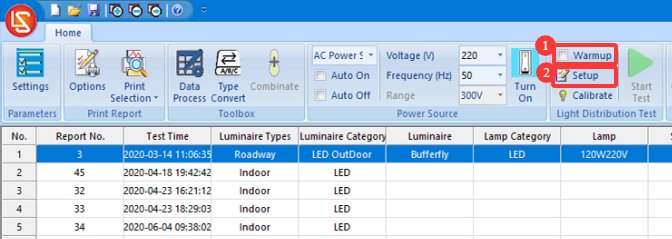
Figura 8-6
Fare clic su "Impostazioni parametri di preriscaldamento".
| Numero | Note: |
|---|---|
| ① | Impostazione della durata del riscaldamento: lo scopo del riscaldamento è quello di consentire all'apparecchio di illuminazione di rimanere acceso per un certo periodo di tempo fino a quando i suoi parametri di luminosità e colore si stabilizzano, dopodiché il test procede automaticamente. |
| ② | Intervallo di campionamento: il software preleverà automaticamente campioni all'intervallo impostato durante l'intero periodo di riscaldamento per ottenere dati in tempo reale. Si consiglia di impostare l'intervallo a 5 secondi o più. |
| ③ | If this box is checked, the test will automatically skip the remaining warm-up time and begin once the light fixture has reached a stable state; if this box is not checked, the warm-up will complete for the set duration before the test begins. |
| ④ | Definition of a luminaire’s steady-state condition. If the settings are 20 and 0.5%, the luminaire is considered to be in a steady state if the parameter has not varied by more than 0.5% over the past 20 minutes. |
| ⑤ | È possibile selezionare quali parametri il software deve utilizzare per determinare se un apparecchio di illuminazione è stabile: parametri ottici, parametri elettrici |
| ⑥ | Il software salverà nel report di prova le curve di variazione dei parametri selezionati durante il periodo di riscaldamento. |
| ⑦ | Una volta terminata la configurazione delle impostazioni, fai clic su OK per salvare e uscire. |
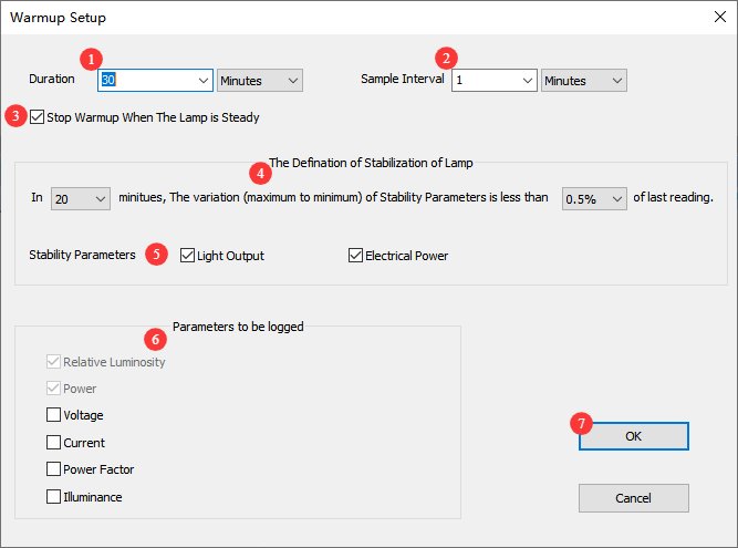
Figura 8-7
8.3 Configure Test Parameters and Start the Test
Fare clic su "Avvia test".
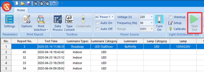
Figura 8-8
Go to the test parameter settings screen and select the type of light fixture you want to test.
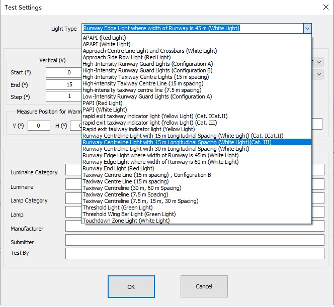
Figure 8–9
Other parameter settings.
| Numero | Note: |
|---|---|
| ① | V-angle test range, angle intervals |
| ② | H-angle test range, angle intervals |
| ③ | For the test speed, just select “normal speed.” |
| ④ | Select the monitoring angle during the warm-up; the (0, 0) position is usually sufficient. |
| ⑤ | Enter the temperature and humidity of the test environment |
| ⑥ | Inserisci le informazioni di esempio |
| ⑦ | Click OK to go to the warm-up screen, or to start the test. |
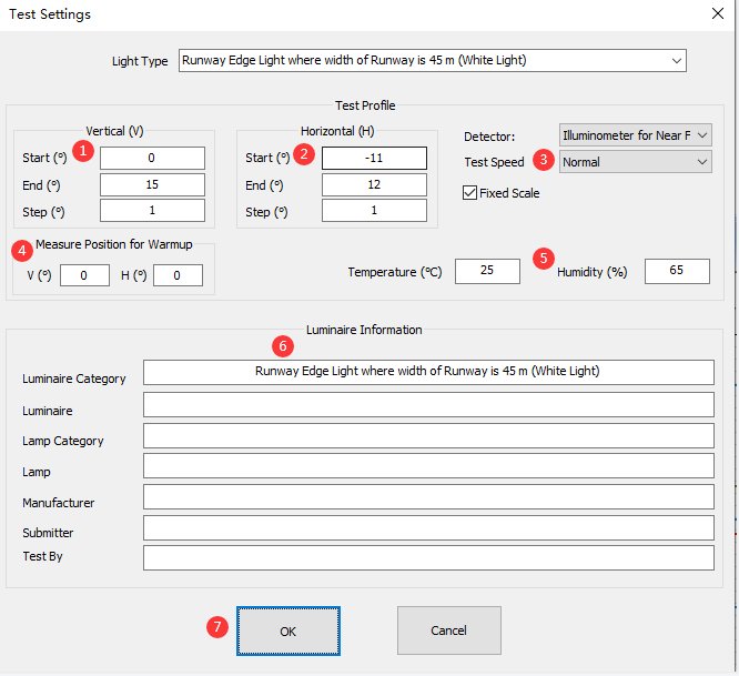
Figure 8–10
The following shows the interface during the testing process. Simply wait for the test to finish.
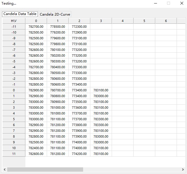
Figure 8–11
8.4 Print the Test Report
Conferma le opzioni di stampa e stampa il rapporto di prova.
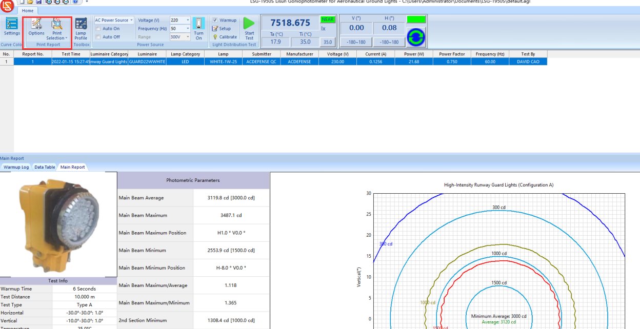
Figure 8–11
9Manutenzione e cura quotidiana delle attrezzature.
9.1 Manutenzione ordinaria
Procedura di avvio: Innanzitutto, accendere l'interruttore principale dell'armadio; quindi, accendere uno alla volta gli interruttori di alimentazione delle apparecchiature all'interno dell'armadio e nella camera oscura; infine, avviare il software. Procedura di arresto: Innanzitutto, chiudere il software; quindi, spegnere uno alla volta gli interruttori di alimentazione delle apparecchiature all'interno dell'armadio e nella camera oscura; infine, spegnere l'interruttore principale dell'armadio.
Mantieni la sala di controllo della camera oscura pulita e priva di polvere per evitare che questa penetri nelle apparecchiature. Se è presente polvere sulla superficie delle apparecchiature, puliscila con un panno morbido e asciutto.
Evitate di esporre la camera oscura a un'umidità elevata per periodi prolungati; tenete a portata di mano un deumidificatore, se necessario.
9.2 Manutenzione regolare
9.2.1 Cleaning the Photometric Probe
If the darkroom cannot be kept dust-free, clean the photosensitive surface of the photometer probe periodically (such as once a month) based on actual conditions to prevent dust from accumulating and affecting test accuracy.
Durante la pulizia, si prega di utilizzare un panno professionale privo di lanugine per rimuovere la polvere senza graffiare il dispositivo.
9.2.2 Lampada standard
La lampada standard ha una validità di un anno. Se dopo un anno è ancora necessario calibrare la camera oscura, si consiglia di acquistare una nuova lampada standard.
9.2.3 Software
Aggiorneremo periodicamente il software per aggiungere nuove funzionalità e correggere eventuali bug. Qualora riscontraste problemi durante l'utilizzo del software, non esitate a contattarci in qualsiasi momento per ottenere la versione più recente.
9.3 Long-Term Decommissioning and Maintenance
9.3.1 Equipment Cleaning and Protection
Thoroughly clean all equipment surfaces, cover the main unit, probes, and cabinet with dust-proof cloths, and disconnect all power sources.
9.3.2 Environmental Protection
Assicurati che la camera oscura sia asciutta e ben ventilata per evitare che le attrezzature si inumidiscano. Se l'umidità ambientale è elevata, tieni a portata di mano un deumidificatore.
9.3.3 Monthly Power-On
Eseguire un test di accensione una volta al mese per assicurarsi che tutto l'hardware del sistema funzioni correttamente.
10Risoluzione dei problemi e delle problematiche più comuni.
10.1 Communication errori
Causa del problema: verificare che il cavo di comunicazione sia collegato saldamente e che non sia inserito nella porta sbagliata; verificare che i driver siano installati correttamente; provare una porta USB o un cavo di comunicazione diverso per escludere problemi hardware.
Soluzione: Reinstallare il driver, collegare il cavo di comunicazione in base all'identificativo del dispositivo, riavviare il software e riprovare.
10.2 Errori in Intensità luminosa Collaudo
Causa del malfunzionamento: Verificare la stabilità della sorgente luminosa e il tempo di riscaldamento sufficiente; accertarsi che la calibrazione dell'apparecchiatura sia valida, che la distanza di prova sia corretta e che la luce standard funzioni correttamente; verificare la presenza di interferenze luminose esterne nella camera oscura e che il percorso della luce non sia ostruito.
Soluzione: prolungare il tempo di riscaldamento, ricalibrare lo strumento, spegnere le altre fonti di luce nella camera oscura e rimuovere eventuali ostruzioni dal percorso ottico.
10.3 The Goniophotomoeter does not rotate
Causa del malfunzionamento: Verificare che l'unità principale sia accesa e che il cablaggio sia corretto; verificare che il regolatore di angolo all'interno del quadro elettrico funzioni correttamente; accertarsi che non vi siano corpi estranei incastrati nell'albero rotante.
Soluzione: Verificare l'alimentazione e il cablaggio, rimuovere eventuali oggetti estranei; riavviare il sistema e il software, quindi riprovare.
10.4 Guasti del software
Causa del problema: verifica di aver effettuato l'accesso al sistema operativo del computer con un account amministratore; verifica che il software sia installato correttamente; verifica che i file del database non siano danneggiati.
Soluzione: Accedere al computer con un account amministratore; reinstallare il software e i driver; creare un nuovo file di database.
10.5 Mancanza di corrente
10.5.1 DC Power Output Abnormalities
Cause del malfunzionamento: l'interruttore AC/DC sull'armadio non era impostato su DC; la tensione o la corrente del campione superavano i limiti dell'alimentatore DC; un cortocircuito nel campione;
Risoluzione dei problemi: Verificare che la tensione e la corrente del campione rientrino nell'intervallo di uscita dell'alimentatore CC. Ad esempio, DC3005 Il modello ha una tensione di uscita massima di 30 V e una corrente di uscita massima di 5 A. Verificare se il campione è in cortocircuito; in tal caso, riparare il campione prima di ripetere il test.
10.5.2 No AC Output
Cause of the fault: The AC/DC switch on the cabinet was not set to the AC position; the overload protection was triggered;
Troubleshooting Steps: Check the AC power output wiring and sample connections to ensure there are no loose connections or short circuits; if the overload protection is triggered, turn off the power, let the unit cool for 5 minutes, and then restart it. Ensure that the sample power remains within the AC power output range—for example, the LSP-500VARC ha una potenza di uscita massima di 500 W.