
 Inglese
 中文简体
中文简体 Русский
 Español
 Português
 Türkçe
 العربية
 Deutsch
 Polski
 Italiano
 Français
 한국어
한국어 ไทย
ไทย Tiếng Việt
 日本語
日本語





























Sistema di sfere integrate con spettroradiometro di alta precisione
Manuale d'uso
Applicabile LISUN modelli: LMS-9000C,LMS-9000CVIS-NIR,LMS-9500C,LMS-9500CVIS-NIR,LPCE-2(LMS-9000C),LPCE-2(LMS-9500C)
1. Disimballaggio e familiarizzazione di base con l'apparecchiatura
1.1 Specifiche tecniche chiave
| Modello | LMS-9000C | LMS-9000CUV-VIS | LMS-9000CVIS-NIR | LMS-9000CUV |
| Lunghezza d'onda | 350-800 nm | 200-800 nm | 350-1050 nm | 200-400 nm |
| Modello | LMS-9500C | LMS-9500CUV-VIS | LMS-9500CVIS-NIR | LMS-9500CSWIR |
| Lunghezza d'onda | 350-800 nm | 200-800 nm | 350-1050 nm | 800-1700 nm |
1.2 Disimballaggio e ispezione
Quando si disimballa il dispositivo, maneggiarlo con delicatezza per evitare di graffiare l'involucro esterno con oggetti appuntiti. Dopo averlo disimballato, ispezionare innanzitutto l'esterno del dispositivo per assicurarsi che non vi siano deformazioni o ammaccature visibili e che i pulsanti non siano danneggiati o allentati. Se si riscontrano anomalie nel dispositivo o nei suoi accessori, non accenderlo. Si prega di contattarci immediatamente.
1.3 Configurazione e panoramica del sistema
1.3.1 Componenti hardware principali
Nota: la tabella seguente elenca i componenti hardware principali dell'intero sistema. L'apparecchiatura acquistata potrebbe includere solo alcuni di questi componenti; si prega di tenerne conto quando si seguono le istruzioni contenute in questo manuale.
| Nome Componente | Modello | Caratteristiche principali |
| High-Precision Spectroradiometer | LMS-9000C/LMS-9500C Campionati | Measure spectral data and calculate chromaticity and photometric parameters |
| Grande sfera integratrice | Modello: IS-*MA Note: * indicates the diameter Integrating Sphere ; standard sizes are: 1 m, 1.5 m, 1.75 m, 2 m, 2.5 m, and 3 m |
Provides a uniform diffuse reflection environment and collects optical signals from samples for testing large samples |
| Sfera integratrice piccola | Modello: IS-*M Note: * indicates Integrating Sphere ; standard sizes are: 0.3 m/0.5 m |
Provides a uniform diffuse reflection environment and collects optical signals from samples for testing small samples |
| Stage | / | It must be installed inside Integrating Sphere (with a diameter of at least 1 m) to allow users to mount the standard lamp and the luminaire under test. |
| Strip Light Fixtures | Applicable only to Integrating Sphere with a diameter of at least 1.5 m. During use, it can be mounted on either side of the stage to facilitate the installation of linear lights, such as LED tubes. | |
| Apparecchio di illuminazione ausiliario | Installed inside Integrating Sphere large Integrating Sphere (with a diameter of at least 1 m) for mounting auxiliary lights | |
| Laser a linee incrociate | Installed inside Integrating Sphere large Integrating Sphere (with a diameter of at least 1.5 m) to determine the center of Integrating Sphere | |
| Mobile | CASE-19 | Designed to hold Spectroradiometer, power meter, and DC and AC power supplies. Includes a power strip, an RS-232 communication module, and more. |
| Misuratore di potenza | Serie LS | Misurare i parametri elettrici quali tensione, corrente, potenza e fattore di potenza del campione. |
| Generatore di corrente continua | Serie DC | Fornisce un'alimentazione CC stabile per campioni CC, lampade di riferimento e lampade ausiliarie. |
| Alimentazione AC | Serie LSP | Fornisce un alimentatore CA stabile e a onda sinusoidale pura per campioni CA |
| Optical Fiber + Probe | CFO+PHOTO Series | Transmit the optical signal from Integrating Sphere to the spectrometer |
| Luce standard | Serie SLS | Integrating Sphere System for Calibrating Spectroradiometer |
| Luci ausiliarie | Serie RLS | Applicable only to Integrating Sphere (with a diameter of at least 1 m). Used to correct for the self-absorption effect of large luminaires and improve test accuracy. |
1.3.2 Software, manuali, certificati, ecc.
Al momento della spedizione, è stato inviato via email un link per scaricare tutti i documenti. Si prega di scaricarli il prima possibile. Se non avete ricevuto l'email, potete anche contattarci direttamente per richiedere un nuovo link per il download.
Include software, manuali utente, schede di garanzia, certificati di calibrazione delle lampade standard e altri documenti importanti, nonché altri documenti pertinenti.
1.4 Parametri di misurazione
| Parametri di cromaticità | Chromaticity coordinates, correlated color temperature, color ratio, peak wavelength, half-width, dominant peak wavelength, color purity, color rendering index, CQS, TM-30-24 (Rf, Rg), spectrograms, etc. |
| Parametri Fotometrici | Luminous flux, luminous efficacy, radiant power, WPE, EQE, EEI, energy efficiency rating, pupillary luminous flux, pupillary luminous flux efficiency, pupillary factor, PAR and PPF for plant growth lights |
| Parametri elettrici | Voltage, Current, Power, Power Factor, Phase Shift Factor (DF), Harmonics |
| Optical Throughput Retention Rate Test | Luminous Flux vs. Time, Color Temperature vs. Time, Color Rendering Index vs. Time, Power vs. Time, Power Factor vs. Time, Current vs. Time, Luminous Efficiency vs. Time |
2. Precauzioni per l'uso
2.1 Sicurezza elettrica
The system must be connected to a stable single-phase 220 V AC, 50/60 Hz power source, and ensure proper grounding with a grounding resistance of ≤1 Ω;
Non utilizzare l'apparecchiatura se i collegamenti di alimentazione sono allentati o i cavi sono danneggiati.
2.2 Sicurezza ambientale
L'apparecchiatura deve essere collocata in un ambiente asciutto e ben ventilato, privo di polvere e gas corrosivi;
Temperatura ambiente: 15–35 °C; umidità relativa: ≤65% (senza condensa);
Tenere l'apparecchiatura lontana da campi magnetici e campi elettrici intensi.
2.3 Using Integrating Sphere
2.3.1 Protezione del rivestimento interno
Whenever entering the interior of Integrating Sphere to perform tasks (such as installing samples or standard lamps), white gloves must be worn; direct contact with the interior coating is prohibited;
Do not use paper towels, rags, or other materials that come into direct contact with the coating to clean it. If dust accumulates, open Integrating Sphere and use a hair dryer Integrating Sphere “cool” setting to blow the dust out from the inside toward the outside (at least once a week);
Assicurarsi di fissare saldamente il campione durante l'installazione per evitare che cada e danneggi il rivestimento; se una piccola area del rivestimento interno si stacca, contattare LISUN per procurarsi materiali per la riparazione dei rivestimenti;
If the coating inside Integrating Sphere has peeled off over a large area, or if the coating has darkened significantly due to lack of proper care, please replace Integrating Sphere.
2.3.2 Integrating Integrating Sphere Switching and Handling
Keep Integrating Sphere closed when not in use to prevent dust from entering;
Do not disassemble Integrating Sphere during transport. If disassembly is necessary under special circumstances, be sure to protect the internal coating from contamination;
2.4 Procedure operative standard per le lampade
The standard lamp has a lifespan of one year and must be replaced when it expires;
La lampada standard è calda subito dopo l'uso; non toccarla. Lasciarla raffreddare per 10 minuti prima di riporla nell'alloggiamento.
Evitate che la superficie della lampada da terra si macchi; se si sporca, pulitela prima dell'uso o sostituitela con una nuova;
Integrating Sphere of different sizes must be used with standard lamps of the corresponding wattage (50W or 100W for large Sphères, and 10W for small Sphères).
2.5 Optical Optical Fiber Operating Procedures
Optical Fiber must not be bent excessively (minimum bend radius ≥ 10 cm). Do not step on or squeeze Optical Fiber, as this may cause damage and result in abnormal test results.
2.6 Altro
Per questioni non trattate in questo manuale, si prega di procedere con cautela o di contattarci.
3. Assemblaggio hardware
3.1 Montaggio delle apparecchiature del mobile
3.1.1 Introduzione al Gabinetto
Posizionare il mobile su un banco da lavoro stabile e robusto, lasciando spazio sufficiente per le operazioni.
A wiring diagram is affixed to the inside of the rear door of the cabinet. Please assemble the equipment inside the cabinet according to the wiring diagram (see Figure 3-1).
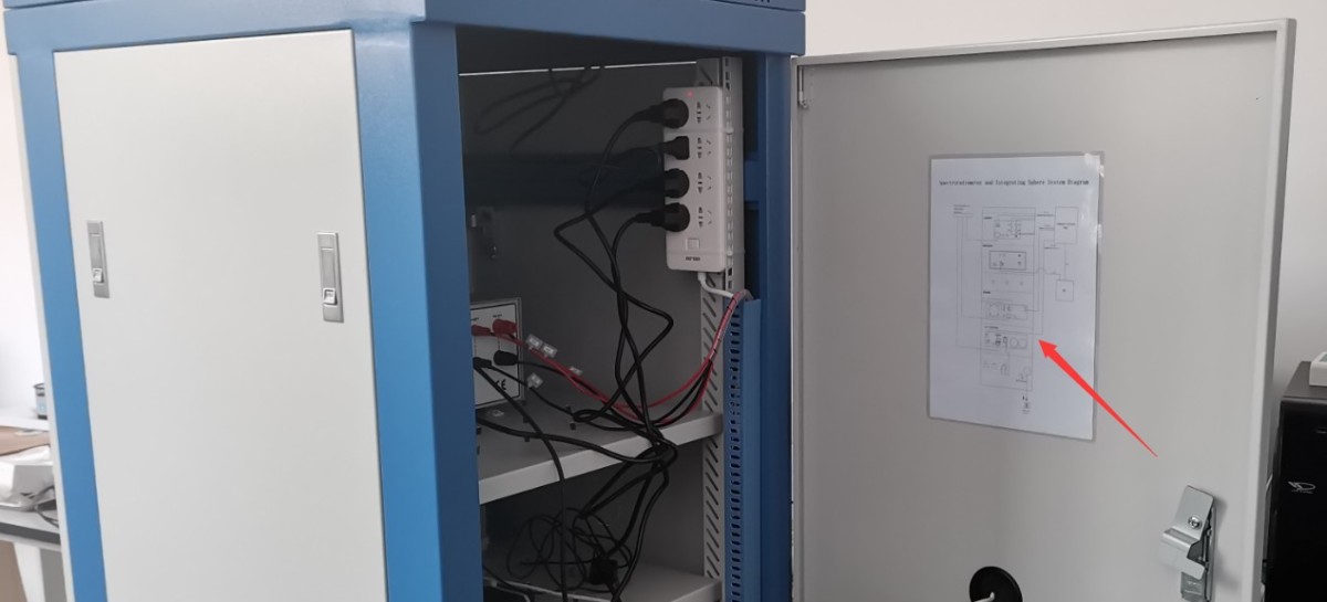
Figura 3-1
The necessary wiring for the equipment inside the cabinet has already been connected, as shown in Figure 3-2.
| Numero | Note: |
| ① | RS-232 Communication Box, used to connect RS-232 communication cables between devices inside a cabinet |
| ② | Power distribution panel, used to connect the power cords of equipment inside the cabinet. Please ensure that the power switch on the power distribution panel is in the “On” position. |
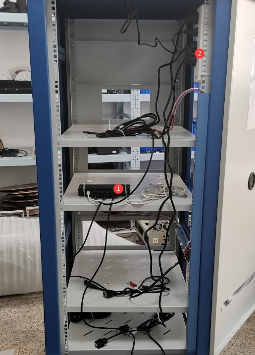
Figura 3-2
Main power cord for the cabinet; see Figure 3-3.
| Numero | Note: |
| ① | Main power cable for the cabinet, used to supply power to all equipment inside the cabinet |
| ② | Feed it through this cable opening, and connect it to an appropriate power source once the equipment is fully assembled. |
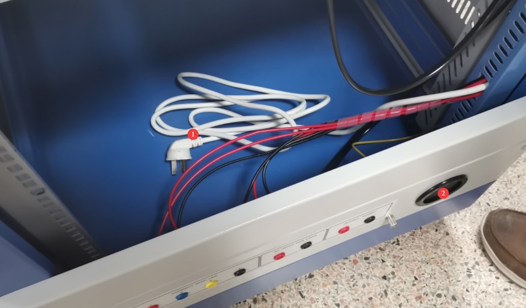
Figura 3-3
3.1.2 Installazione del misuratore di potenza LS
Vedere le figure 3–4.
| Numero | Note: |
| ① | Il collegamento avviene tramite un cavo di comunicazione RS-232; l'altra estremità è collegata alla scatola di comunicazione RS-232 all'interno dell'armadio. |
| ② | Il puntale di prova V1 è collegato al terminale rosso della tensione V del misuratore di potenza. |
| ③ | V2 test lead, connected to the black terminal of the power meter’s V voltage |
| ④ | Puntale di prova A1, collegato al terminale rosso della corrente A del misuratore di potenza |
| ⑤ | Puntale di prova A2, collegato al terminale nero della corrente A del misuratore di potenza |
| ⑥ | Il cavo di alimentazione è collegato; l'altra estremità è già collegata alla ciabatta all'interno del mobile. |
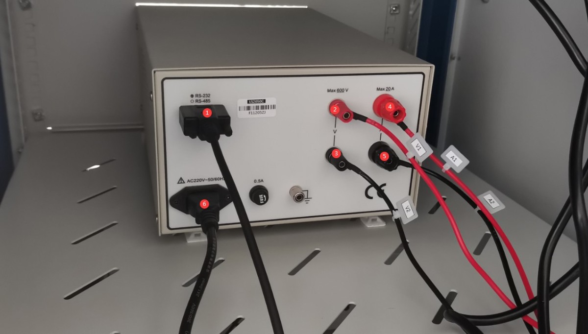
Figura 3-4
3.1.3 Installation of the Spectroradiometer
Spectroradiometer; see Figures 3–5:
| Numero | Note: |
| ① | Cavo USB |
| ② | Sonda di luminanza |
| ③ | Fibra ottica |
| ④ | Termometro |
| ⑤ | Power adapter (included with select models only) |
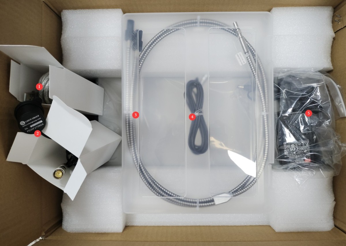
Figura 3-5
To connect Spectroradiometer see Figure 3-6:
| Numero | Note: |
| ① Optical Fiber | The other end must be connected to Integrating Sphere. If your device includes two Integrating Sphere, use a Y-shaped Optical Fiber splitter to connect to both Integrating Sphere simultaneously. |
| ② Photometric Probe | The probe end must be connected to Integrating Sphere. If your device has two Integrating Sphere, simply connect the probe to Integrating Sphere; Integrating Sphere does not need to be connected to the photometer probe. |
| ③ Temperature Probe | The probe end must be connected to Integrating Sphere. If your device has two Integrating Sphere, simply connect it to Integrating Sphere Integrating Sphere you are using. |
| ④ USB cable | Connect the other end to your computer. Do not use any other USB extension cables or USB adapters, as this may cause Spectroradiometer to malfunction. If you are using a desktop computer, connect it to a black or blue USB port on the back of the computer case. |
| ⑤ Power Jack | Migliori LMS-9000C is powered and communicates via USB, so no power adapter is required. However, if your Spectroradiometer is an LMS-9500C, LMS-9000CUV-VIS, or similar, we will include a 5V power adapter in the package. Please be sure to connect the power adapter here as well. OtherwiseSpectroradiometer will not function properly. |
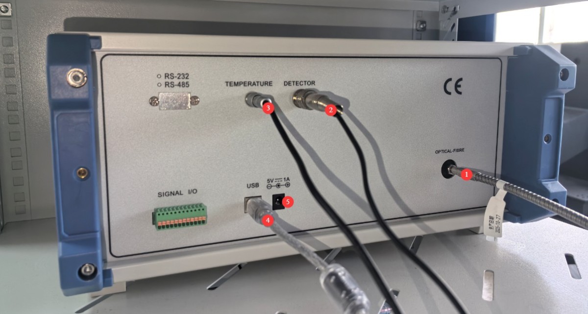
Figura 3-6
3.1.4 Installazione dell'alimentatore CC
Vedere Figura 3-7.
| Numero | Note: |
| ① | Il collegamento avviene tramite un cavo di comunicazione RS-232; l'altra estremità è collegata alla scatola di comunicazione RS-232 all'interno dell'armadio. |
| ② | Collegare i fili di uscita dell'alimentazione CC, assicurandosi di far corrispondere i terminali positivo e negativo. |
| ③ | Il cavo di alimentazione è collegato; l'altra estremità è già collegata alla ciabatta all'interno del mobile. |
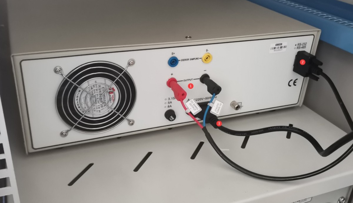
Figura 3-7
3.1.5 Installazione dell'alimentazione CA
Please locate the following AC power output cord in the accessories, as shown in Figure 3-8:
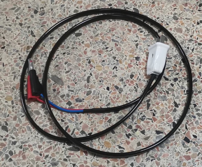
Figura 3-8
AC Power Installation—see Figures 3-9 and 3-10:
| Numero | Note: |
| ① | Far passare il cavo di uscita dell'alimentazione CA attraverso l'apertura per cavi ④ e collegarlo alla posizione ⑤. |
| ② | Il collegamento avviene tramite un cavo di comunicazione RS-232; l'altra estremità è collegata alla scatola di comunicazione RS-232 all'interno dell'armadio. |
| ③ | Il cavo di alimentazione è collegato alla presa; l'altra estremità è già connessa alla ciabatta all'interno del mobile. |
| ④ | Foro del filo |
| ⑤ | Run the AC power output cable through cable opening ④ and connect it to position ①. |
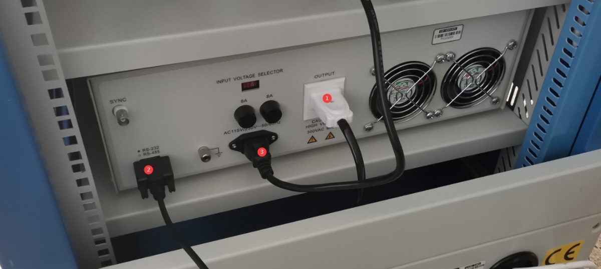
Figura 3-9
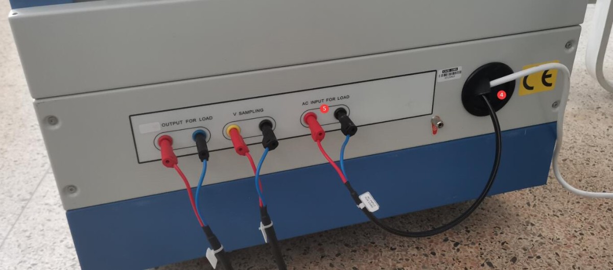
Figura 3-10
3.1.6 Connecting the RS232 Modulo di comunicazione
See Figure 3-11: Connect the other end of the communication box’s USB cable to the computer. Do not use other USB extension cables or USB adapters, as this may cause communication errors. If using a desktop computer, connect the cable to a black or blue USB port on the back of the computer.
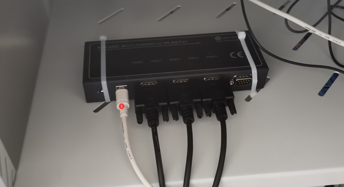
Figura 3-11
3.2 Assemblaggio e messa in servizio di accessori per sfere integratrici di grandi dimensioni
3.2.1 Mount Installation and Connection
To prevent Integrating Sphere large Integrating Sphere from opening during shipping, we secure Integrating Sphere with screws. Please remove the two screws securing Integrating Sphere, as shown in Figure 3-12.
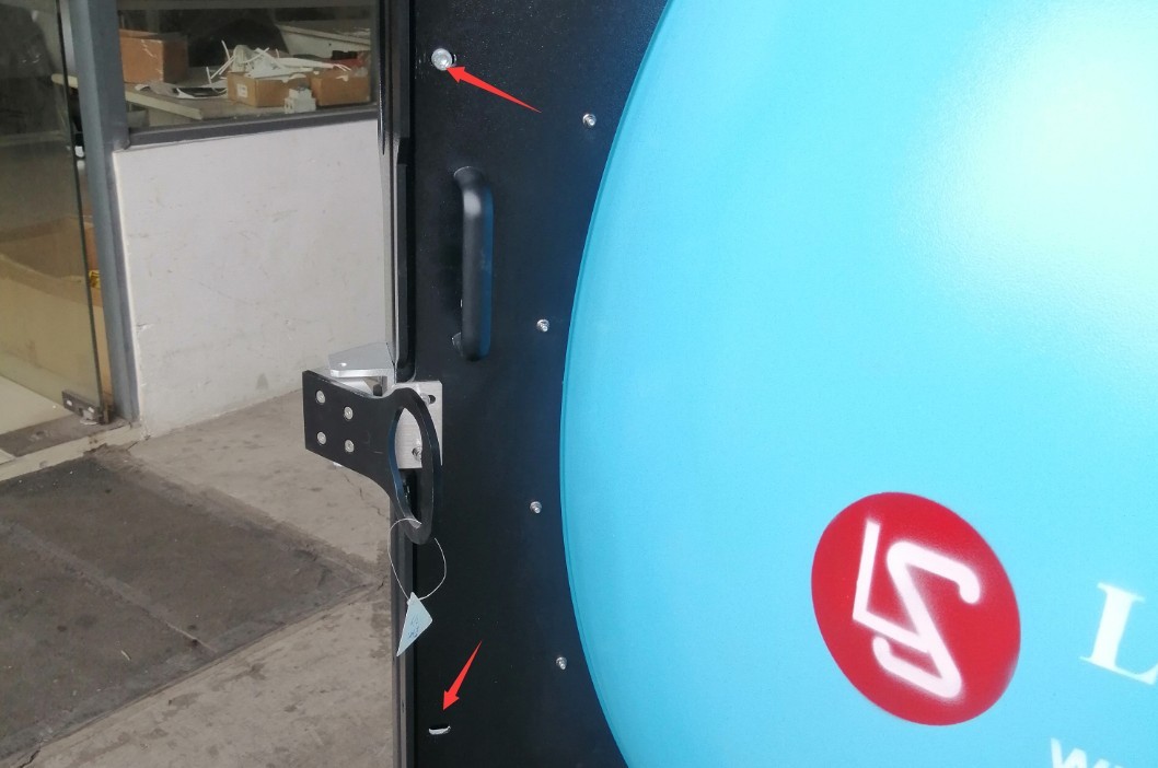
Figura 3-12
The stage can be mounted either on top of Integrating Sphere Integrating Sphere or at the bottom. This section uses the example of mounting the stage at the bottom. Open Integrating Sphere, loosen this screw, and remove the plug, as shown in Figure 3-13.
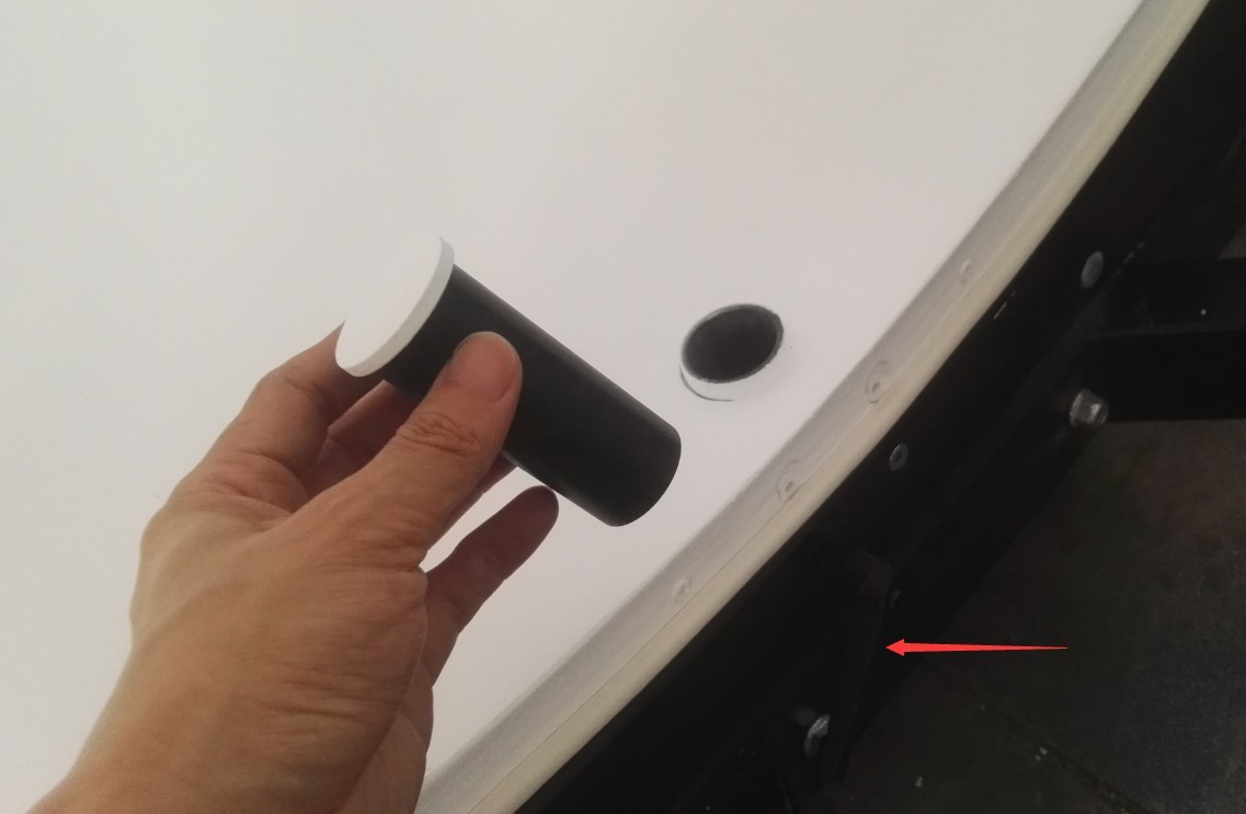
Figura 3-13
Feed the four-core cable from the stage through the opening at the bottom of Integrating Sphere, as shown in Figure 3-14.
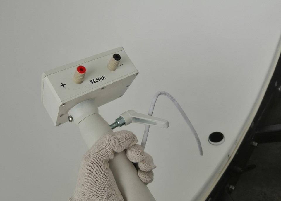
Figura 3-14
Refer to Figure 3-15, then retighten this screw, making sure the screw handle is facing down.
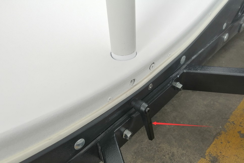
Figura 3-15
Connect the junction box as shown in Figures 3-16 and 3-17.
| Numero | Note: |
| ① | Connect the four-wire cable from the stage to the back of the junction box at the base of Integrating Sphere large Integrating Sphere. The four terminals on the junction box—POWER and SENSE—must be connected one-to-one with the four terminals on the stage—POWER and SENSE. You can open the stage and the junction box to verify this. |
| ② | Connect the two “POWER” terminals on the Integrating Sphere junction box to the “OUTPUT FOR LOAD” terminals on the cabinet. |
| ③ | Connect the two terminals on the Integrating Sphere junction box (SENSE) to the cabinet’s V SAMPLING port. |
| ④ | Connect the two “OUTPUT FOR LOAD” terminals on the cabinet to the “POWER” terminal on the Integrating Sphere junction box. |
| ⑤ | Connect the two “V SAMPLING” terminals on the cabinet to the “SENSE” terminal on the Integrating Sphere junction box. |
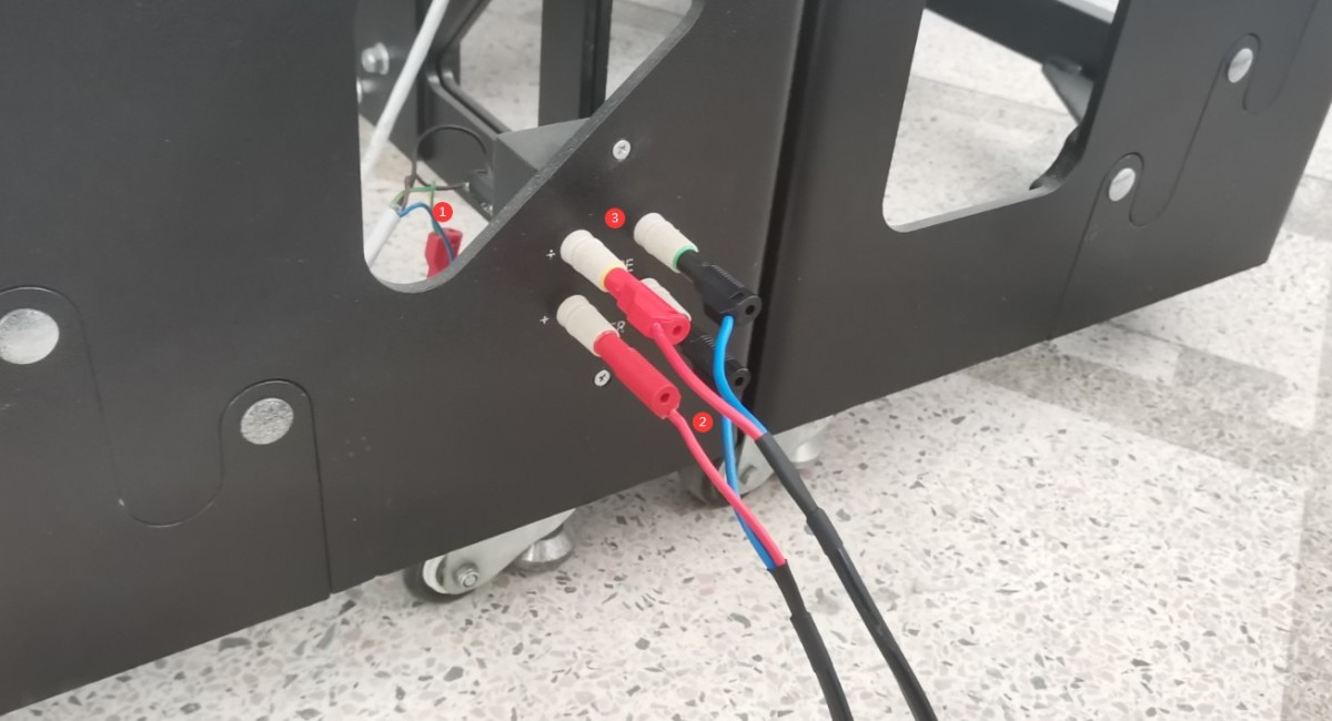
Figura 3-16
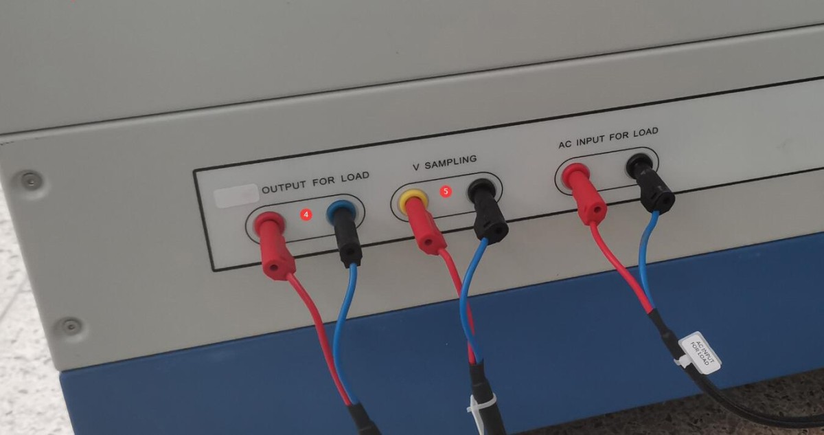
Figura 3-17
Note: If your device includes two Integrating SphèresIntegrating Sphere when Integrating Sphere the smaller Integrating Sphere, Integrating Sphere Integrating Sphere four-wire cable from the cabinet to the larger Integrating Sphere to the smaller Integrating Sphere.
3.2.2 Connecting Spectroradiometer Accessories
Vedere Figura 3-18.
| Numero | Note: |
| ① | Fibra ottica |
| ② | Sonda di luminanza |
| ③ | Sonda di temperatura |
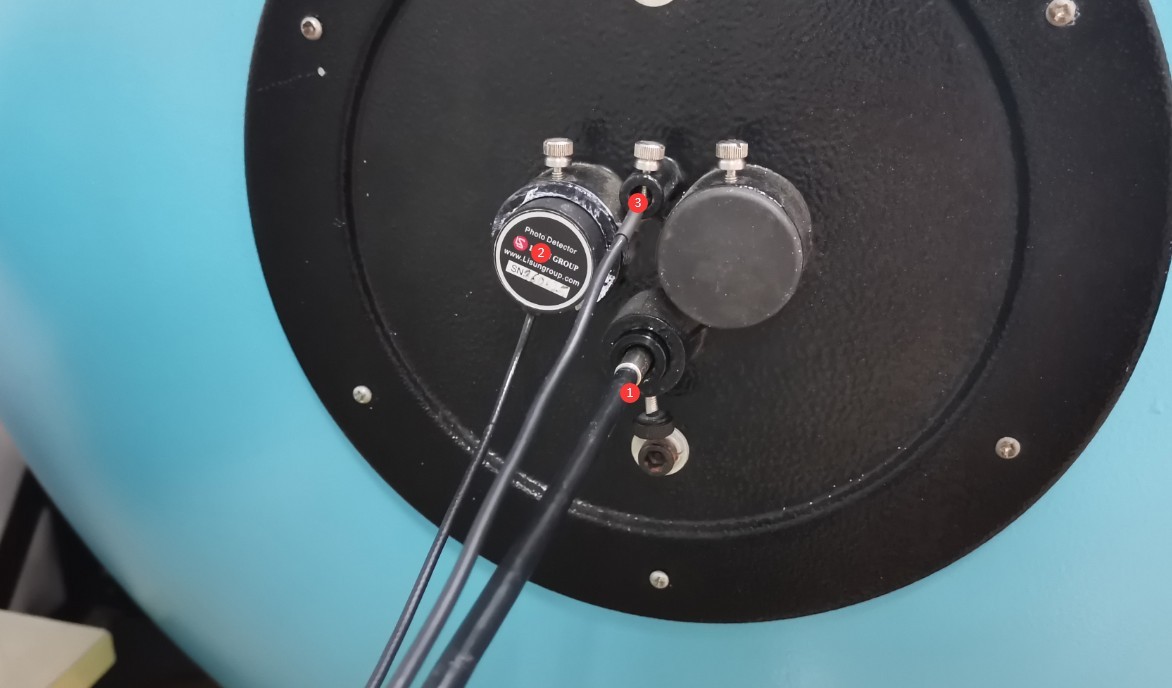
Figura 3-18
Note: If your device includes two Integrating Sphere, connect the other end of Optical Fiber Y-shaped Optical Fiber to Integrating Sphere smaller Integrating Sphere.
3.2.3 Calibrazione laser incrociata
Integrating Sphere contains a cross-shaped laser, as shown in Figure 3-19.
| Numero | Note: |
| ① | Battery compartment, used to power the cross-line laser |
| ② | Interruttore laser a linea incrociata |
| ③ | Mirino laser e relative viti di montaggio |
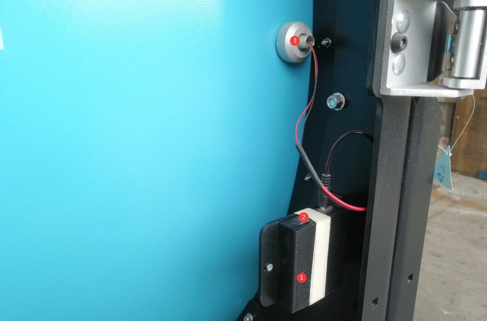
Figura 3-19
Turn on the crosshair laser. The crosshair laser may have become misaligned during shipping. Use a tape measure to confirm the center position of Integrating Sphere, loosen the screw securing the crosshair laser, reposition the crosshair laser so that it is exactly centered on Integrating Sphere, and then tighten the screw securely.
3.3 Power On and Off Procedures
Connect the cabinet power cord to a 220 V, 50/60 Hz power source, as shown in Figure 3-20.
| Numero | Note: |
| ① | Cabinet Power Switch |
| ② | Internal sampling/external sampling, voltage sampling methods. Internal sampling is the older, three-wire sampling method specified in the old standard, while external sampling is the newer, four-wire sampling method specified in the new standard. Simply switch to external sampling; there is no need to use internal sampling. |
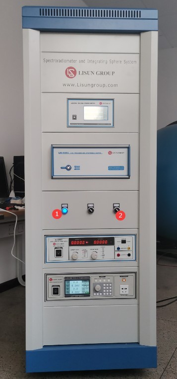
Figura 3-20
Sequenza di accensione: innanzitutto, accendere l'interruttore di alimentazione principale dell'armadio, quindi accendere uno alla volta gli interruttori di alimentazione di ciascuna apparecchiatura all'interno dell'armadio.
Procedura di spegnimento: innanzitutto, spegnere singolarmente gli interruttori di alimentazione di ciascuna apparecchiatura all'interno dell'armadio, quindi spegnere l'interruttore di alimentazione principale dell'armadio.
4. Installazione e configurazione del software
4.1 Installazione del software e dei driver
4.1.1 Ambiente di runtime del software
Requisiti di sistema: Windows 7/8/10/11 (32 bit/64 bit); il computer deve disporre di almeno due porte USB.
Note: If you have purchased multiple LMS-9000 units, please connect them to different computers whenever possible and avoid mixing them, as doing so may cause the software to display incorrect data.
Installazione 4.1.2
Vedere Figura 4-1.
| Numero | Note: |
| ① | LMS-9000 software—please double-click to install |
| ② | LMS-9000 Driver—please double-click to install |
| ③ | RS232 Communication Box Driver—please double-click to install |
| ④ | Windows Plug-in: If you encounter an error message from the Windows operating system while installing the LMS-9000 software, you may need to install this plug-in. |

Figura 4-1
4.1.3 Gestione delle eccezioni
Se il software antivirus o il Firewall di Windows segnalano un file come sospetto durante il processo di installazione del software, disattivate temporaneamente il software antivirus o il Firewall di Windows e provate a installare nuovamente il software.
If the software fails to open when you double-click the icon after a successful installation, please check whether you are logged in to your computer with an administrator account. If the software still does not open after logging in with an administrator account, right-click the software icon to open its Properties window. On the Compatibility tab, check the box next to “Run this program as an administrator,” click “Apply,” and then double-click the icon again to open the software, as shown in Figure 4-2.
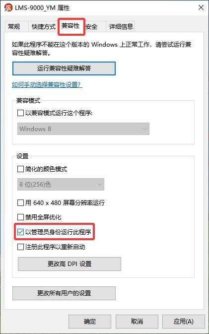
Figura 4-2
4.1.4 Visualizzare Gestione dispositivi sul computer
Open “Device Manager” on your computer (see Figure 4-3). You should find “LMS-9000” and four additional communication ports in the following location (Note: Port numbers may vary depending on the computer and USB port used), and verify that there are no error messages. If any abnormalities are found, please refer to sections 4.1.2 and 4.1.3 for troubleshooting and verification.
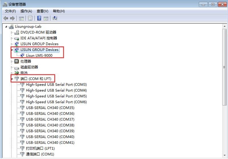
Figura 4-3
Nota: se il dispositivo non include un RS232 modulo di comunicazione, le quattro porte di comunicazione aggiuntive menzionate sopra non verranno visualizzate in "Gestione dispositivi" del computer.
4.2 Impostazioni del software
4.2.1 Apertura del software
When you open the software for the first time, you will be prompted to create a new database file (in .lms format), as shown in Figure 4-4. Subsequent test reports will be automatically saved in this database file. Please enter a file name, select an appropriate path, and click “Save.”
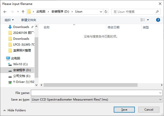
Figura 4-4
Note 1: The LMS-9000 can be installed on any computer; however, the software will not function unless the computer is communicating with the LMS-9000 device.
Nota 2: I file di database generati dal software LMS-9000 possono essere aperti solo utilizzando il software LMS-9000.
Nota 3: Si prega di evitare, quando possibile, di posizionare i file del database sul desktop del computer, poiché ciò potrebbe causare errori durante la lettura o la scrittura dei dati.
4.2.2 Adding Large and Small Integrating Sphere
If your system includes two Integrating Sphere, click “Add Large Sphere” and “Add Small Sphere” at the locations shown in the figure below (see Figures 4-5).
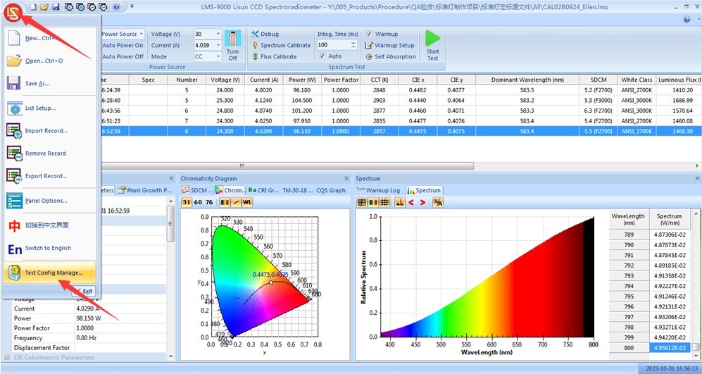
Figure 4–5
When you modify or add the corresponding test options, they will be displayed as tabs in the location shown in the figure below (see Figure 4-6):
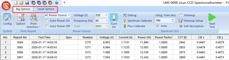
Figure 4–6
All software operations—including system configuration, calibration, testing, and the generation and use of auxiliary light coefficients—must be performed under the corresponding test configuration tab.
4.2.3 Configurazione del sistema
Take Integrating Sphere as an example. Select the “Large Integrating Sphere Sphere” tab and click “System Configuration,” as shown in Figure 4-7.
| Numero | Note: |
| ① | Spectroradiometer models and related information; the software can retrieve this information automatically |
| ② | The default maximum integration time is 2000 milliseconds. The LMS-9500C is a refrigerated model that can still produce accurate test reports even when light signals are very faint. However, longer integration times are required in such situations. If you are using the LMS-9500C Spectroradiometer, you can increase the integration time to, for example, 10000 milliseconds to facilitate testing in low-light conditions. |
| ③ | Click the drop-down list to select the photometric parameter measurement method. As mentioned above, Spectroradiometer is connected to the Integrating Sphere Sphere via an Optical Fiber a photometric probe. If you have two Integrating Sphere and the Integrating Sphere is connected via Optical Fiber, you should select “Spectroradiometric Method”; if only Integrating Sphere smaller Integrating Sphere is connected via Optical Fiber you should select “Spectrometric Method.” |
| ④ | Wavelength measurement range settings: The default range is 380 to 800 nm. If the wavelength range of Spectroradiometer you purchased is different, please adjust the settings here directly. |
| ⑤ | Fai clic sull'elenco a discesa per selezionare il modello dell'alimentatore CA che hai acquistato (di solito la serie LSP). Se non hai acquistato un LISUN Se si tratta di un alimentatore CA, selezionare "Non installato"; in caso contrario, si verificherà un errore di comunicazione. |
| ⑥ | Fai clic sull'elenco a discesa per selezionare il modello dell'alimentatore CC che hai acquistato (di solito la serie CC). Se non hai acquistato un LISUN Se si tratta di un alimentatore CC, selezionare "Non installato"; in caso contrario, si verificherà un errore di comunicazione. |
| ⑦ | Fai clic sull'elenco a discesa per selezionare il modello del misuratore di potenza che hai acquistato; puoi trovare il numero del modello sul pannello frontale del misuratore di potenza. Seleziona il modello corretto che hai acquistato. Se non hai acquistato un LISUN Se si tratta di un contatore di potenza, selezionare "Non installato"; in caso contrario, si verificherà un errore di comunicazione. |
| ⑧ | Enter the dimensions Integrating Sphere. This information appears only in the test report and does not affect the actual test results. |
| ⑨ | Se hai acquistato un file TMP-8 Multiplex Temperature Tester to use with Spectroradiometer, click the drop-down list to select the corresponding Multiplex Temperature Tester model. Once communication is established, Spectroradiometer may display the temperatures measured by Multiplex Temperature Tester in the test report as well. |
| ⑩ | Click “Auto-Search Ports.” If a message indicates a communication error with a device, follow the on-screen instructions to verify that the correct model has been selected, that the communication cable is connected, and that the device is powered on. |
| ⑪ | Una volta configurate tutte le impostazioni e la comunicazione, è sufficiente fare clic su OK per salvare. |
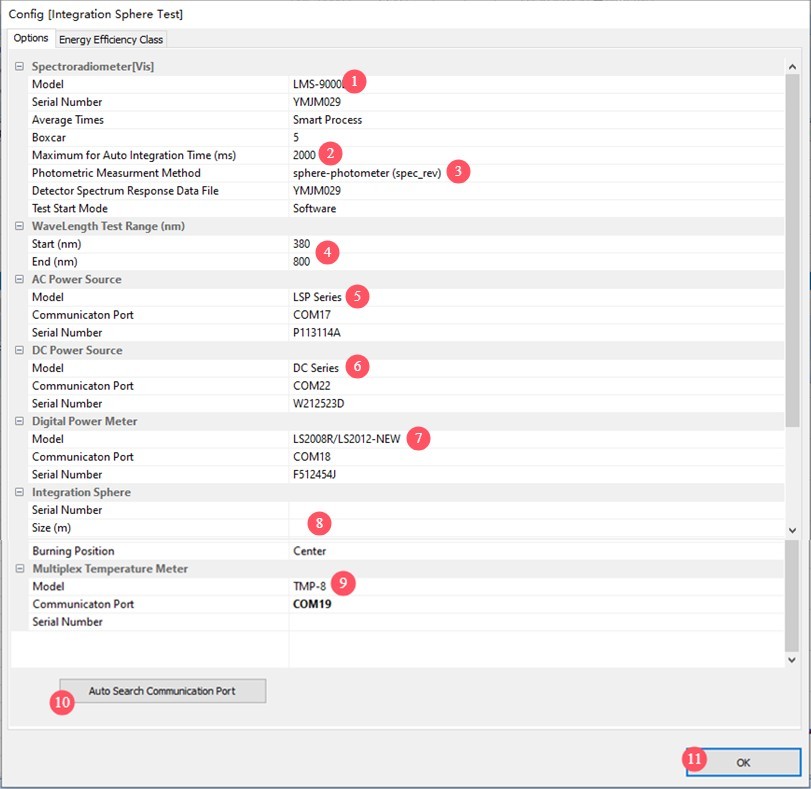
Figure 4–7
Note 1: Switch the software interface to “Small Integrating Sphere Sphere” and configure all settings using the same method.
Nota 2: Reinstallare il software o scollegare e ricollegare il cavo USB richiederà il ripristino della comunicazione.
5. Calibrazione
5.1 Principi di calibrazione
| Descrizione della situazione | È necessaria la ricalibrazione? |
| Primo utilizzo | La calibrazione è necessaria prima dell'uso. |
| L'attrezzatura deve essere utilizzata ogni settimana. | Si consiglia di effettuare la calibrazione una volta alla settimana. |
| Attrezzatura che non è stata utilizzata per più di una settimana | Prima del successivo utilizzo è necessaria la calibrazione. |
| Reinstallare il software | Nessuna ricalibrazione richiesta |
| Sostituisci il computer | Necessita di ricalibrazione |
| Collegare e scollegare il cavo USB | Nessuna ricalibrazione richiesta |
| Inserting and Removing the Optical Fiber Probe on the Spectrometer End | |
| Inserting and Removing the Optical Fiber Probe from Integrating Sphere | Si consiglia di ricalibrare. |
| Cambiamenti significativi nelle condizioni ambientali, come temperatura e umidità | |
| The software has added Integrating Sphere and Integrating Sphere | Calibration must be performed separately, and the calibration data for the Integrating Sphere does not affect the calibration data for the Integrating Sphere; each must follow the principles outlined above. |
5.2 Calibration Procedure for Integrating Sphere
Take Integrating Sphere large Integrating Sphere as an example. Refer to Section 3.2.1 to connect the two two-conductor cables from the cabinet—a total of four cables—to the large Integrating Sphere junction box.
All of our standard lamps are constant-current DC light sources. Please set the AC/DC switch on the cabinet to DC, as shown in Figure 5-1.
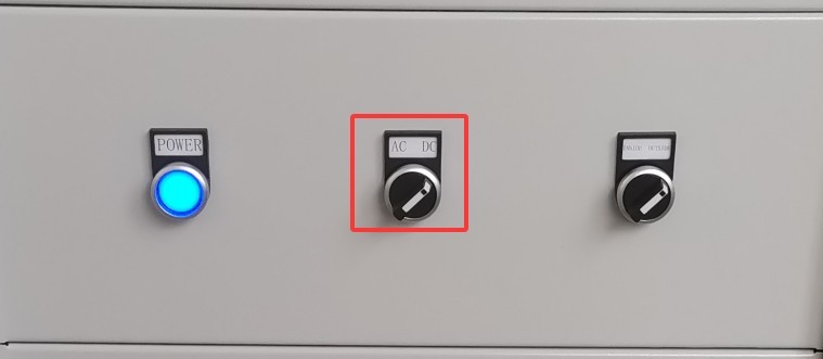
Figura 5-1
Please remove the appropriate standard bulb, put on white gloves, and carefully install it into the E27 socket on the stand. Turn on the crosshair laser to ensure the bulb is centered on the sphere, as shown in Figure 5-2.
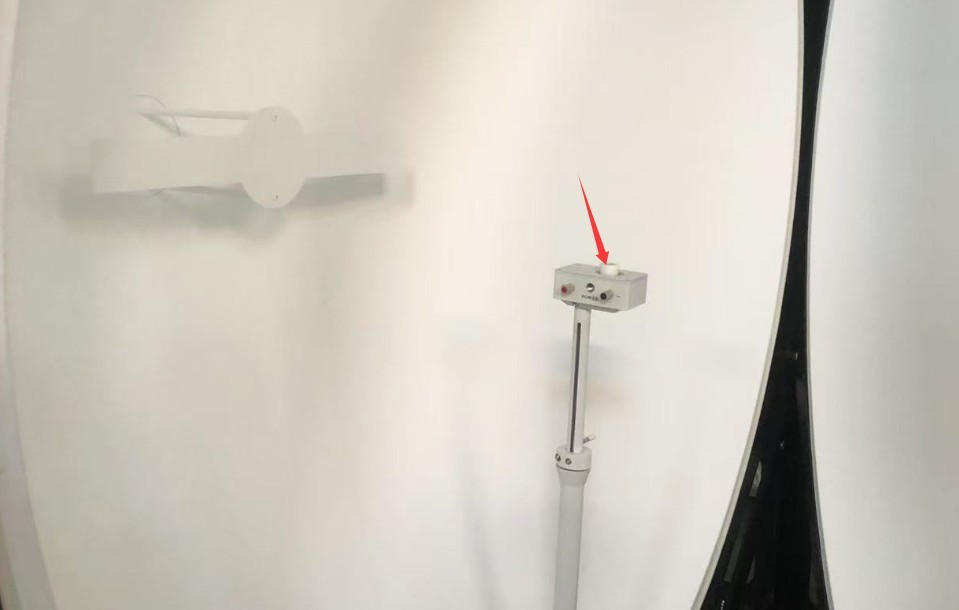
Figura 5-2
Then turn off the crosshair laser and Integrating Sphere. If your device has two Integrating Sphere, make Integrating Sphere both are turned off (Optical Fiber reads signals from Integrating Sphere simultaneously).
Switch the software to “Large Integrating Sphere,” then click “Spectral Calibration,” as shown in Figure 5-3.
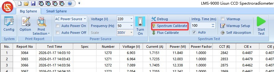
Figura 5-3
Se il tuo software sta già comunicando correttamente con il LISUN DC power supply, please refer to Section 5.2.1 to continue; if your software is not communicating with the LISUN DC power supply, please refer to Section 5.2.2 to continue.
5.2.1 The software is communicating properly with the LISUN generatore di corrente continua
Se hai acquistato un file LISUN DC power supply and have successfully established communication with it in “System Configuration,” please follow the instructions in the table and diagram below, as shown in Figure 5-4.
| Numero | Note: |
| ① | The device automatically displays the DC power supply model and communication port, eliminating the need to select or search for the port again. |
| ② | To make the process more convenient, please check the “Auto-On” and “Auto-Off” options. |
| ③ | The corresponding current and voltage values are listed on the standard lamp certificate and the standard lamp packaging box; please enter them correctly. Note: The specifications vary by lamp, so please do not mix and match them. |
| ④ | Click to control the DC power supply output and verify that the test lamp illuminates properly. When the test lamp is lit normally, the DC power supply should display “CC” (constant current output), and the displayed current value should match the input value exactly; the displayed voltage will fluctuate around 25V. If the displayed current does not match the entered value (fluctuations in the last digit after the decimal point are normal) or if the displayed voltage differs significantly (for example, only around 10 V), the standard lamp is not lighting up properly. Please check the standard lamp’s filament, its installation, and all wiring, then try again. |
| ⑤ | The color temperature and luminous flux are listed on the standard lamp certificate and the standard lamp packaging. Please enter them correctly. Note: The specifications vary by lamp; please do not mix them. |
| ⑥ | Per accumulare punti, assicurati di selezionare la casella "Automatico". |
| ⑦ | Average count; the default is 10; no changes are needed. |
| ⑧ | The warm-up time is set to 15 minutes by default; no changes are necessary. In other words, after clicking “Start,” the software will wait 15 minutes for the standard lamp to warm up, and once the data has stabilized, it will automatically perform calibration. |
| ⑨ | Once you have confirmed that the above settings are correct, click “Start.” The software will automatically perform the following steps in this order: automatically control the DC power supply to turn on the standard lamp; start the warm-up countdown; automatically perform calibration when the warm-up countdown ends; and, after successful calibration, automatically control the DC power supply to turn off the standard lamp. |
| Note: | In the calibration interface, do not perform any actions on the sections not listed in this table! |
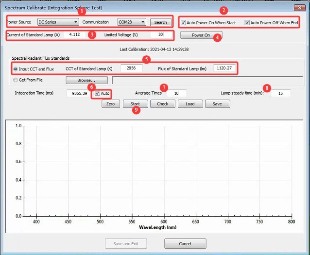
Figura 5-4
After successful calibration, the following interface will appear, as shown in Figure 5-5.
| Numero | Note: |
| ① | Check whether the color temperature and luminous flux displayed here match or are close to the set values. A difference of 1 to 2 K in color temperature and 1 to 2 lumens in luminous flux is considered normal. |
| ② | Fai clic su "Salva ed esci" per completare la calibrazione. |
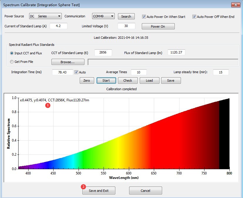
Figura 5-5
The standard lamp will be hot immediately after use. Wait until it has cooled to room temperature, then carefully remove it while wearing white gloves (do not touch the bulb to prevent contamination), and return it to its case for proper storage.
5.2.2 The software is not communicating with the LISUN generatore di corrente continua
Se non hai acquistato un LISUN DC power supply, or if you were unable to establish communication with it in “System Configuration,” please refer to the following table and illustrations for instructions; see Figures 5–6.
| Numero | Note: |
| ① | Do not check the “Auto On” or “Auto Off” options. Do not enter standard lamp current or voltage parameters, and do not click to control the DC power supply output; otherwise, the software will display an error message. |
| ② | The color temperature and luminous flux are listed on the standard lamp certificate and the standard lamp packaging; please enter them correctly. Nota: le specifiche variano a seconda della lampada; non mescolarle. |
| ③ | Per accumulare punti, assicurati di selezionare la casella "Automatico". |
| ④ | Conteggio medio; il valore predefinito è 10; non è necessaria alcuna modifica. |
| ⑤ | The warm-up time is set to 15 minutes by default and does not need to be changed. In other words, after you click “Start,” the software will wait 15 minutes for the standard lamp to warm up, and once its data has stabilized, it will automatically perform calibration. |
| ⑥ | Once you have confirmed that the above operations and settings are correct, manually operate your DC power supply. Refer to the corresponding current value listed on the standard lamp certificate and the standard lamp packaging to ensure constant-current output and turn on the standard lamp. When the standard lamp is lit normally, the DC power supply should display “CC,” indicating constant current output, and the displayed current value should match the entered value exactly. The displayed voltage will fluctuate around 25V. If the displayed current does not match the entered value (fluctuations in the last digit after the decimal point are normal) or the displayed voltage differs significantly (e.g., only around 10V), the standard lamp is not lit properly. Please check the standard lamp’s filament, installation, and all wiring, then try again. Una volta che la lampada standard è accesa normalmente, fare clic su "Avvia". Il software avvierà automaticamente il conto alla rovescia per il riscaldamento. Al termine del conto alla rovescia, la calibrazione inizierà automaticamente. Dopo aver completato la calibrazione, spegnere manualmente la lampada standard utilizzando l'alimentatore CC. |
| Note: | In the calibration interface, do not perform any actions on the sections not listed in this table! |
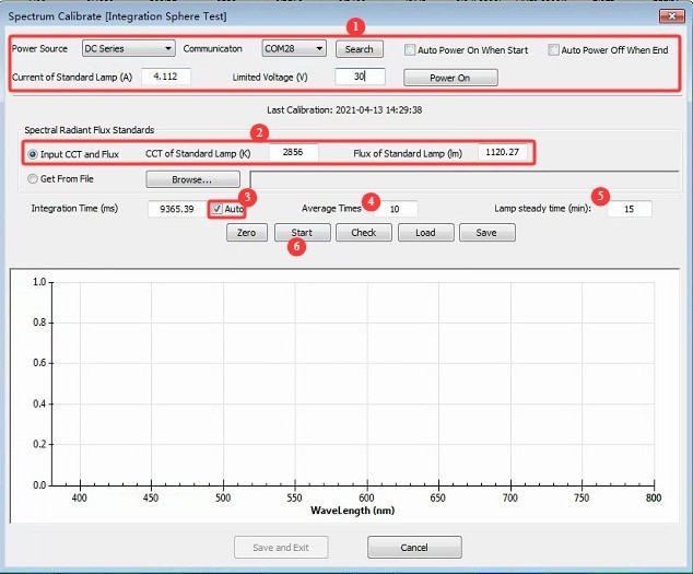
Figure 5–6
After successful calibration, the following interface will appear, as shown in Figure 5-7.
| Numero | Note: |
| ① | Verificate che la temperatura di colore e il flusso luminoso visualizzati siano vicini ai valori impostati. Una differenza di 1-2 K nella temperatura di colore e di 1-2 lumen nel flusso luminoso è considerata normale. |
| ② | Fai clic su "Salva ed esci" per completare la calibrazione. |
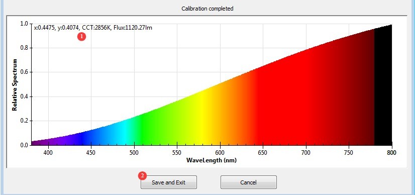
Figura 5-7
The standard lamp will be hot immediately after use. Wait until it has cooled to room temperature, then carefully remove it while wearing white gloves (avoid touching the bulb to prevent contamination), and place it back in the lamp case for proper storage.
5.3 Procedure for Calibrating Integrating Sphere Small Integrating Sphere
Refer to Section 3.2.1 to connect the two two-conductor cables from the cabinet—a total of four cables—to the small Integrating Sphere junction box.
Impostare il software su "Piccola sfera integratrice".
Install the standard bulb. Note: Integrating Sphere 0.3-meter Integrating Sphere does not include an E27 socket. Please wear white gloves and carefully remove the 10W standard bulb so that it can be installed in the 0.3-meter Integrating Sphere Sphere. The 0.5-meter small Integrating Sphere Sphere includes an E27 socket; there is no need to remove the bulb.
Remove the 10W standard light bulb, as shown in Figure 5-8:
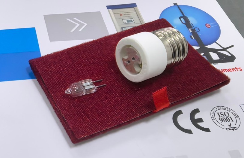
Figura 5-8
All other operations are exactly the same as those for Integrating Sphere; please refer to Section 5.2.
6. Analisi
6.1 Integrating Sphere Test
6.1.1 Calibration Verification
Consultare la Sezione 5.1 per determinare se è necessaria una ricalibrazione.
6.1.2 Installazione di esempio
When the stage is mounted at the bottom, the sample’s light-emitting surface should face upward; when the stage is mounted at the top, the light-emitting surface should face downward—it must not face to the side. Use the crosshairs as a reference to adjust the sample’s position so that its light-emitting surface is exactly in the center of Integrating Sphere. Secure it firmly with screws or clamps to prevent it from falling during testing.
If the sample is an E27 light bulb, it can be mounted directly onto the stage or mounted onto the stage using an E27 adapter; no power cord is required. See Figure 6-1.
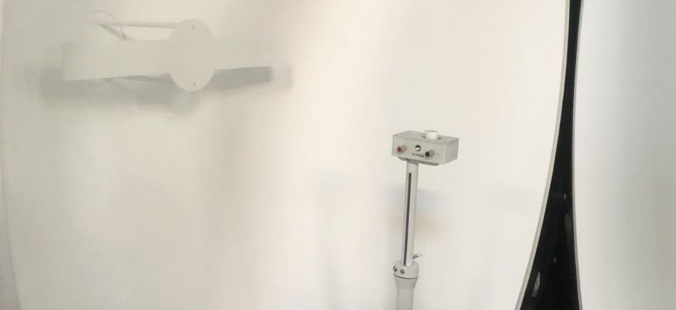
Figura 6-1
If the sample is a linear light fixture, a linear light fixture clamp may be installed and used, as shown in Figure 6-2.
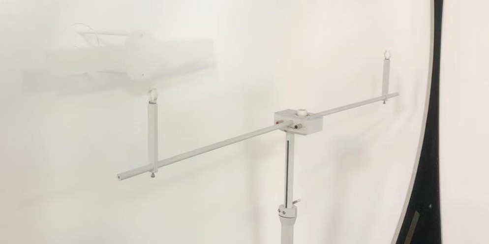
Figura 6-2
For other samples, place them directly on the stage or secure them with screws; the stage is equipped with M6 screw holes. Ensure that they do not fall off; see Figure 6-3.
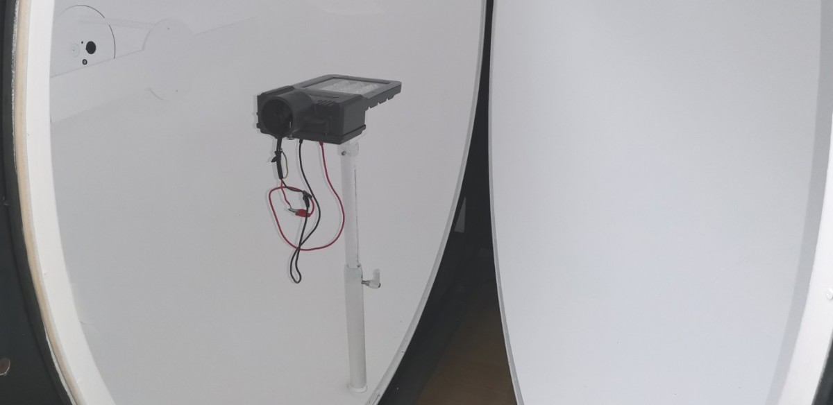
Figura 6-3
Collegare il cavo di alimentazione ai due terminali POWER sul palco; i due terminali SENSE non devono essere collegati. Se si utilizza una lampada alimentata a corrente continua, assicurarsi di collegare correttamente i terminali positivo e negativo.
After installation, turn off the crosshair laser and Integrating Sphere. If your device includes two Integrating Sphere, make Integrating Sphere are turned off at the same time.
6.1.3 Commutazione dell'alimentazione dell'armadio
Se il campione è alimentato in corrente continua (CC), impostare l'interruttore CA/CC sull'armadio sulla posizione CC; se il campione è alimentato in corrente alternata (CA), impostare l'interruttore CA/CC sull'armadio sulla posizione CA.
6.1.4 Verification of the Self-Absorption Coefficient
Integrating Sphere testing relies on diffuse reflection from the Sphere’s walls to take measurements. Therefore, if the sample is a relatively large luminaire, “self-absorption” may occur—that is, some of the diffuse reflected light is absorbed by the luminaire itself—which can cause deviations in the test results. Bare light sources and small luminaires can be tested directly; for larger luminaires, an Auxiliary Lamp must be used for correction, as shown in Figure 6-4.
| Numero | Note: |
| ① | Click “Self-Absorption Coefficient” |
| ② | Per sorgenti luminose nude o apparecchi di illuminazione di piccole dimensioni, selezionare "Non utilizzare una luce ausiliaria per la correzione", che corrisponde a un fattore di correzione pari a 1. Per apparecchi di illuminazione di dimensioni maggiori, selezionare il fattore di correzione appropriato dall'elenco a discesa. Se per questo campione non è stato precedentemente generato alcun fattore di correzione, sarà necessario utilizzare una luce ausiliaria per generarne uno nuovo; fare riferimento al Capitolo 8. |
| ③ | After selecting the correct auxiliary light correction factor, click “OK” to exit this page. |
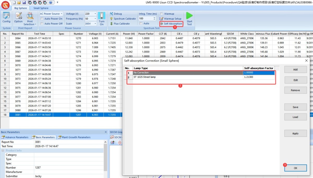
Figura 6-4
Note: Even if the software or computer is shut down, the software will still use the last self-absorption coefficient by default the next time it is opened. Therefore, you must verify that you are using the correct self-absorption coefficient before each test.
6.1.5 Verifica dei parametri di alimentazione tramite navigazione software
If the sample luminaire is powered by AC, see Figure 6-5:
| Numero | Note: |
| ① | Click the drop-down list and select “AC Power.” |
| ② | Enter the correct voltage and frequency for the sample luminaire |
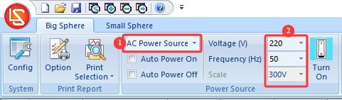
Figura 6-5
If the sample luminaire is powered by a DC power supply, see Figure 6-6:
| Numero | Note: |
| ① | Click the drop-down list and select “DC Power.” |
| ② | Enter the correct voltage and current for the sample lamp. Then select the output mode: CC for constant current mode and CV for constant voltage mode. |
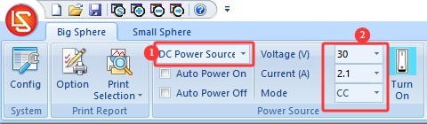
Figura 6-6
Note: If you need CC (Constant Current) mode, enter the sample’s rated current and the power supply’s maximum output voltage; if you need CV (Constant Voltage) mode, enter the sample’s rated voltage and the power supply’s maximum output current. If the sample fails to light up, please verify that the sample’s voltage and current are within the power supply’s output range. For example, the DC3005 Il modello ha una tensione di uscita massima di 30 V e una corrente di uscita massima di 5 A.
6.1.6 Confirmation of EEI Energy Efficiency Rating Settings
Vedere le figure 6–7.
| Numero | Note: |
| ① | Fare clic su “Configurazione di sistema” |
| ② | Switch to the EEI tab |
| ③ | Selezionare le norme applicabili e il tipo di apparecchio di illuminazione |
| ④ | Fare clic su OK per salvare |
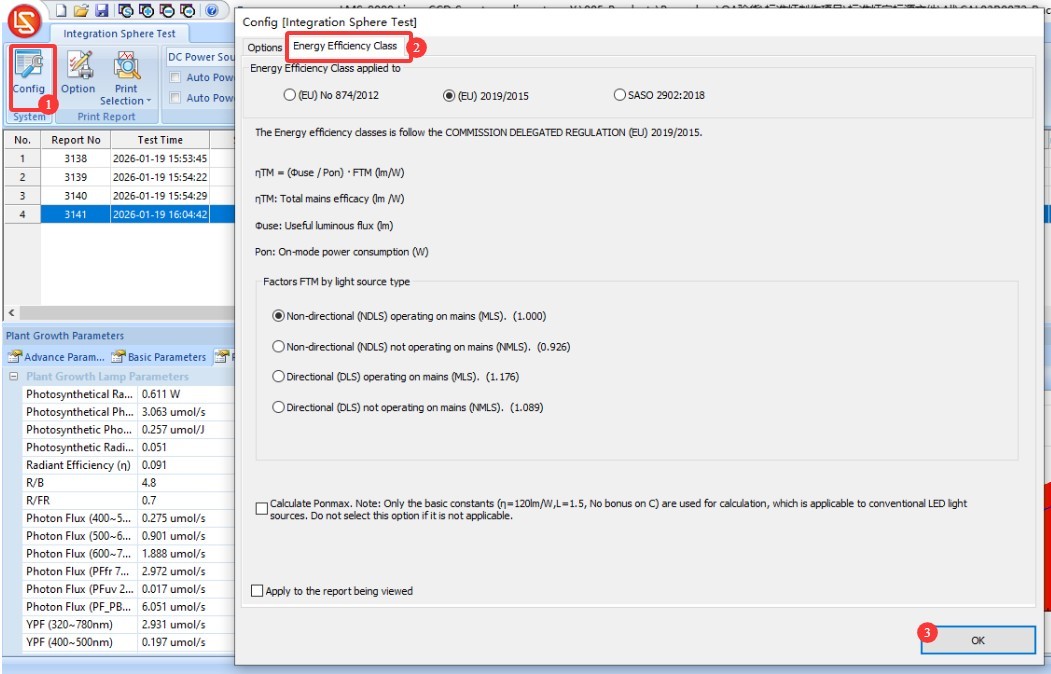
Figure 6–7
6.1.7 Impostazioni dei parametri di preriscaldamento
Vedere le figure 6–8.
| Numero | Note: |
| ① | Fare clic su “Impostazioni parametri di preriscaldamento” |
| ② | Warm-up Duration Setting: The purpose of the warm-up is to allow the light fixture to remain on for a period of time until its luminous and color parameters stabilize, after which the test will proceed automatically. |
| ③ | Intervallo di campionamento: il software preleverà automaticamente campioni all'intervallo impostato durante l'intero periodo di riscaldamento per ottenere dati in tempo reale. Si consiglia di impostare l'intervallo a 5 secondi o più. |
| ④ | If checked, the test will automatically skip the remaining warm-up time and begin once the light fixture has stabilized; if unchecked, the test will begin only after the warm-up period has elapsed as set. |
| ⑤ | If checked, test reports for all sampling points will be saved automatically; if unchecked, only the final test report will be saved automatically. |
| ⑥ | Definition of a luminaire’s steady state. If 20 and 0.5% are set, the luminaire is considered to be in a steady state if the parameter has not varied by more than 0.5% over the past 20 minutes. |
| ⑦ | È possibile selezionare quali parametri il software deve utilizzare per determinare se un apparecchio di illuminazione è stabile: parametri ottici, parametri elettrici |
| ⑧ | The software will save the change curves for the selected parameters during the warm-up period to the test report. |
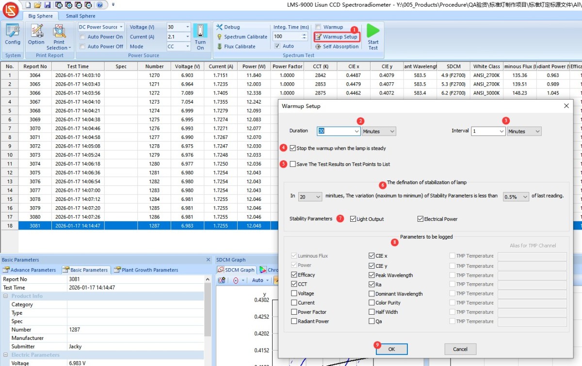
Figure 6–8
6.1.8 Verify the test control parameters and conduct the test
Vedere le figure 6–9.
| Numero | Note: |
| ① | If the “Auto Turn On” and “Auto Turn Off” options are checked, clicking “Test” will cause the software to automatically turn on the light fixture according to the entered electrical parameters. Once the test is complete, the software will automatically turn off the light. Note: If you check the “Auto Turn On” option, you must also check “Preheat.” If you do not enable preheating—that is, if the software turns on the fixture and immediately begins testing—the interval between these actions will be too short, and the test results will not be reliable. |
| ② | If the “Auto On” and “Auto Off” options are not checked, you can also turn the light on or off by tapping this button. |
| ③ | Be sure to select “Automatic” for “Points Time”; otherwise, the test results will be inaccurate. |
| ④ | Se è necessario preriscaldare, spuntare la casella; altrimenti, lasciarla deselezionata. |
| ⑤ | Fai clic per avviare il test. Se l'opzione "Riscaldamento" è selezionata, il software avvierà un conto alla rovescia per il riscaldamento e visualizzerà l'andamento e i dati attuali del riscaldamento nell'angolo in alto a destra; se l'opzione "Riscaldamento" non è selezionata, il software eseguirà il test immediatamente e visualizzerà i risultati. |
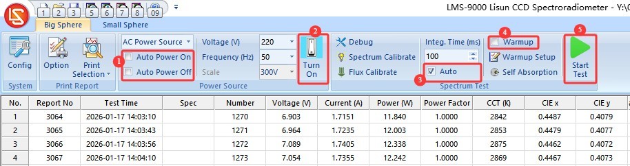
Figure 6–9
During the warm-up process, the software interface appears as shown in Figure 6-10.
| Numero | Note: |
| ① | Questa sezione mostra l'andamento del preriscaldamento, nonché i parametri e la curva di preriscaldamento attuali. |
| ② | Fai clic per saltare il riscaldamento e passare direttamente al test |
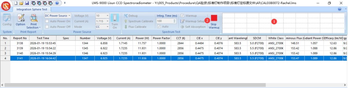
Figura 6-10
After the test is complete, all test reports are automatically saved in the current database file, as shown in Figure 6-11.
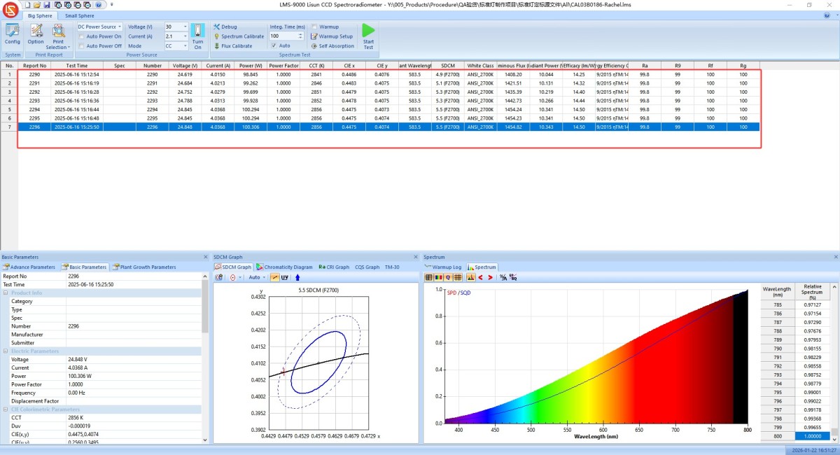
Figura 6-11
Please turn off the power to the sample luminaire and remove it. Do not store the luminaire inside Integrating Sphere when it is not being tested.
6.2 Prova con sfera integratrice di piccole dimensioni
Passare all'interfaccia software "Small Integrating Sphere".
La sfera Xiaoji non è dotata di un alloggiamento per luci ausiliarie, quindi non è necessario applicare alcun fattore di correzione per le luci ausiliarie.
The remaining steps are identical to those in the Integrating Sphere test; please refer to Section 6.1.
7. Elaborazione dei rapporti di prova
7.1 Database File Processing
Vedere Figura 7-1.
| Numero | Note: |
| ① | Per eliminare un report di test dal file del database, selezionare il report e fare clic su "Elimina". |
| ② | Per semplificare la ricerca dei report di prova, fai clic sul pulsante vuoto mostrato nell'immagine sottostante per creare un nuovo file di database e archivia i report relativi ai diversi apparecchi di illuminazione in file di database separati. Dopo aver creato un nuovo file di database, puoi procedere direttamente con i test senza dover ricalibrare o riconfigurare il sistema. |
| ③ | Fai clic su "Apri" per aprire un file di database salvato in precedenza. |
| ④ | Fare clic su OK per salvare |
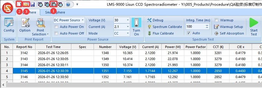
Figura 7-1
Nota 1: Alla successiva apertura del software, verrà caricato automaticamente il file di database utilizzato l'ultima volta. Se il percorso di tale file di database è cambiato o il suo nome è stato modificato, il software richiederà di creare un nuovo file di database.
Nota 2: Evita, se possibile, di posizionare i file del database sul desktop del computer.
7.2 Impostazioni di visualizzazione del rapporto di prova
Adjusting the software interface display. Click the logo in the upper-left corner, then click “Panel Options,” as shown in Figure 7-2.
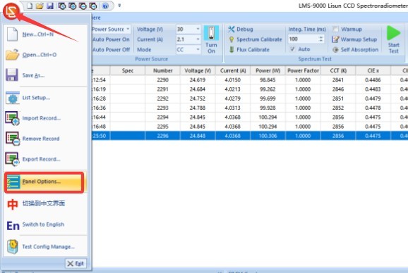
Figura 7-2
The following window appears, as shown in Figure 7-3.
| Numero | Note: |
| ① | You can choose which parameter modules to display on the software interface |
| ② | If checked, the software interface will revert to its default layout the next time it is launched. |
| ③ | Once you’ve configured the device, click OK to save. |
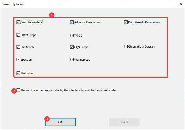
Figura 7-3
You can manually enter the report number and product information, as shown in Figure 7-4.
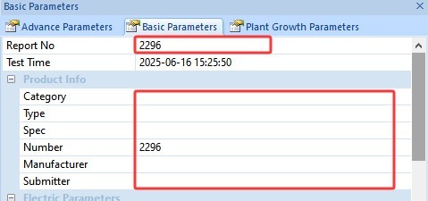
Figura 7-4
You can manually enter the laboratory name and the operator’s name, as shown in Figure 7-5.
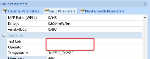
Figura 7-5
7.2 Exporting and Printing Test Reports
Clicca il rosso LISUN logo in the upper-left corner, then select “Export Data” from the drop-down menu, as shown in Figure 7-6:
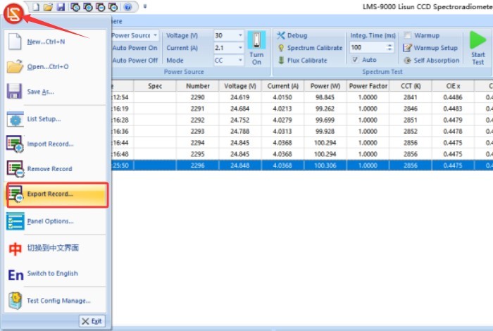
Figura 7-6
Data can be exported in all of the following formats, as shown in Figure 7-7:
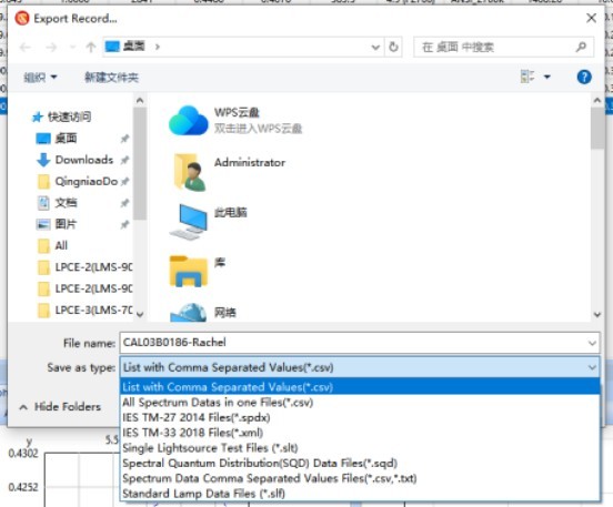
Figura 7-7
Click “Print Options” to configure the content to be displayed in the print report, as shown in Figures 7-8. To ensure the completeness of the test report, you can select all options or choose only those you need. Note: You can select only one of the CIE chromaticity diagram or the SDCM color tolerance diagram.
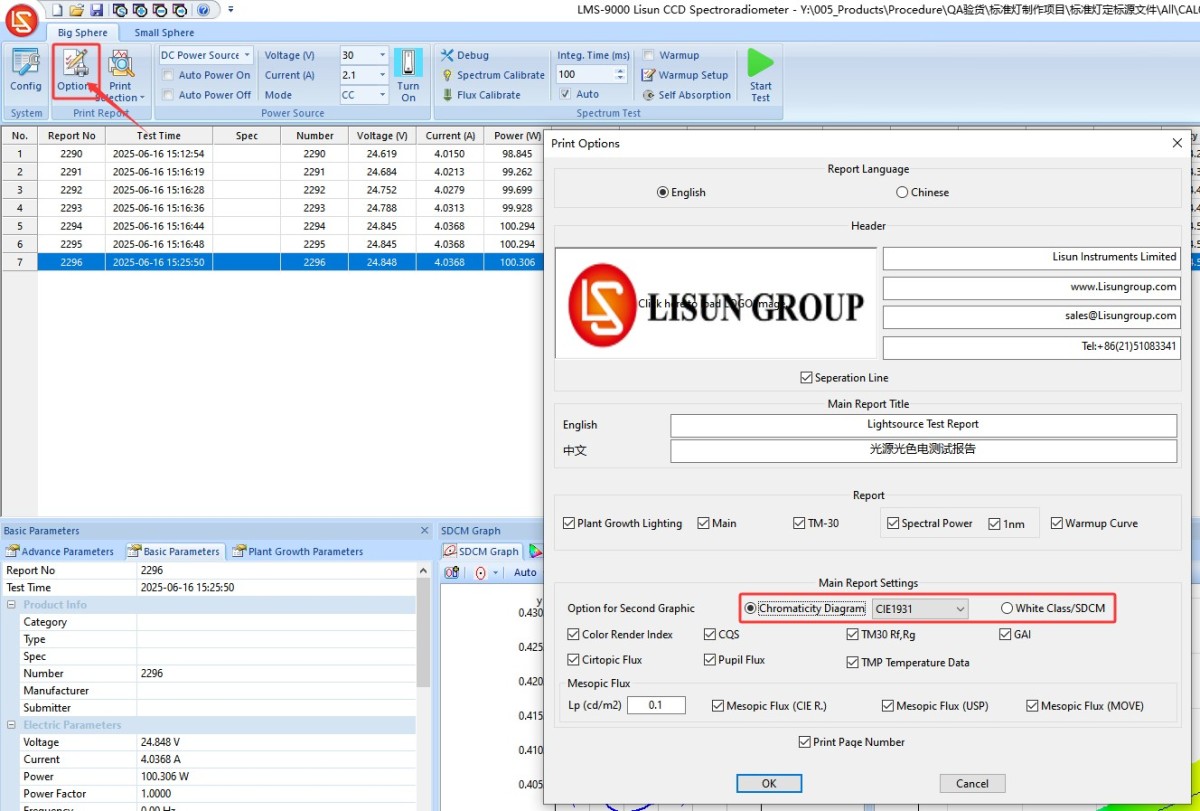
Figure 7–8
To print the test report, your computer must be connected to a printer or have a PDF printer installed, as shown in Figures 7–9.
| Numero | Note: |
| ① | Fare clic per stampare il rapporto di prova attualmente selezionato |
| ② | Click “Print All” in the drop-down list to print all test reports in the current database file. |
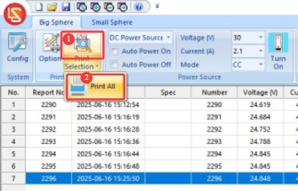
Fig. 7-9
The following shows the print output of the test reports; see Figures 7-10 through 7-13:
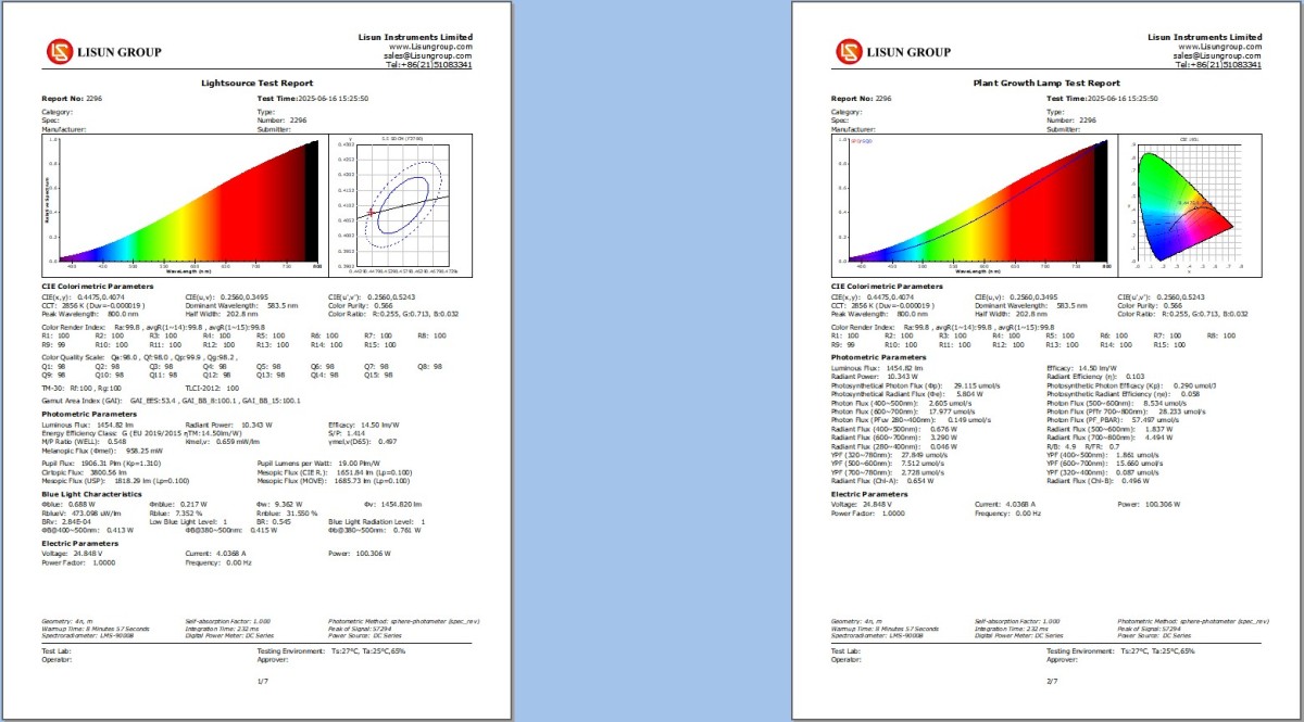
Figure 7–10
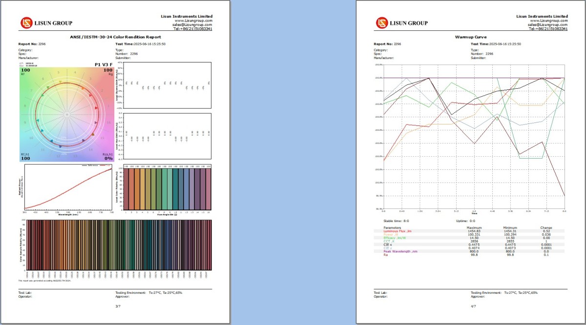
Figura 7-11
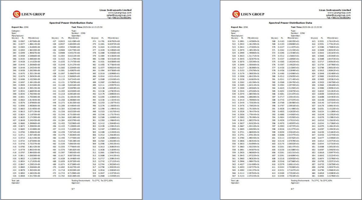
Figura 7-12
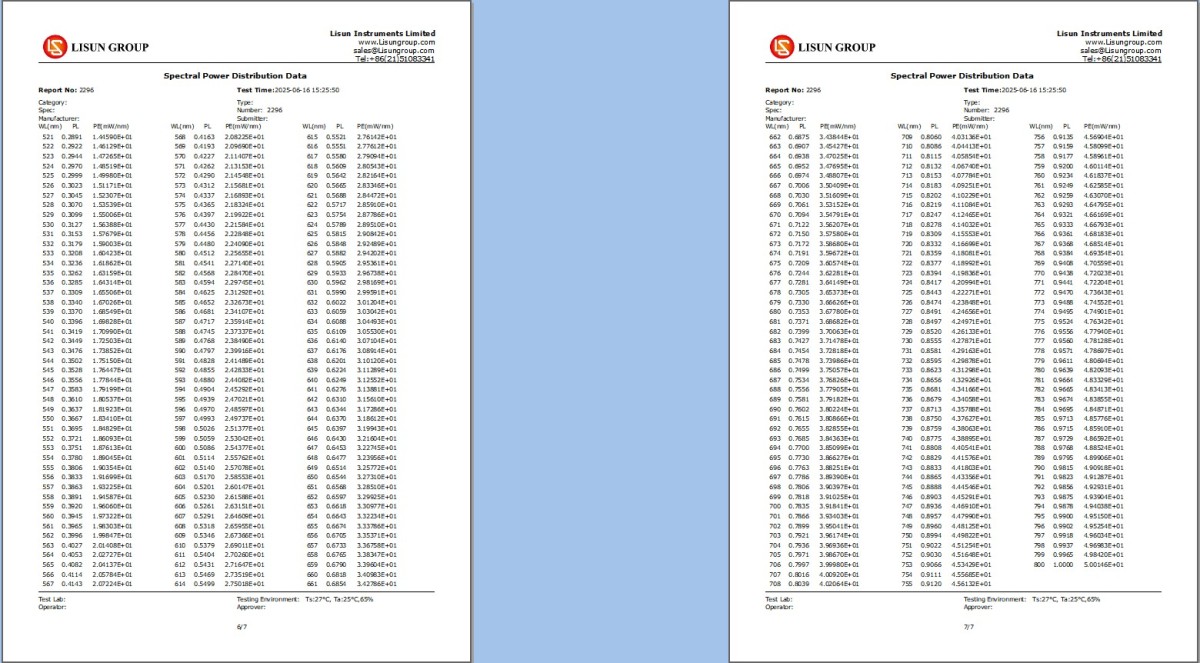
Figura 7-13
8. Generation of the Self-Absorption Coefficient (Use of an Auxiliary Light)
8.1 Scenari di utilizzo delle luci ausiliarie
For larger luminaires, the issue of self-absorption may arise. If a correction factor for the auxiliary light has not been generated previously, you must first generate the correction factor using the auxiliary light before conducting the test. Self-absorption is related to the luminaire’s housing dimensions, shape, color, and other factors; therefore, the self-absorption coefficient varies for different luminaires.
Note: The darker the color of the luminaire and the larger its size, the more severe the “self-absorption” issue becomes. Users can gain practical experience regarding whether to apply an auxiliary light correction factor. For example, for certain small luminaires, if the correction factor obtained after applying the auxiliary light correction factor is 1.02, this indicates that the luminous flux test result will increase by 2% after applying the correction factor; For example, for certain large luminaires, if the correction factor obtained after applying the auxiliary light correction is 1.13, this indicates that the luminous flux test result will increase by 13% after applying the correction factor.
8.2 Installation and Wiring of Auxiliary Lights
① Remove the plug from the opposite side of Integrating Sphere large Integrating Sphere to prepare for installing the auxiliary light fixture; see Figure 8-1.
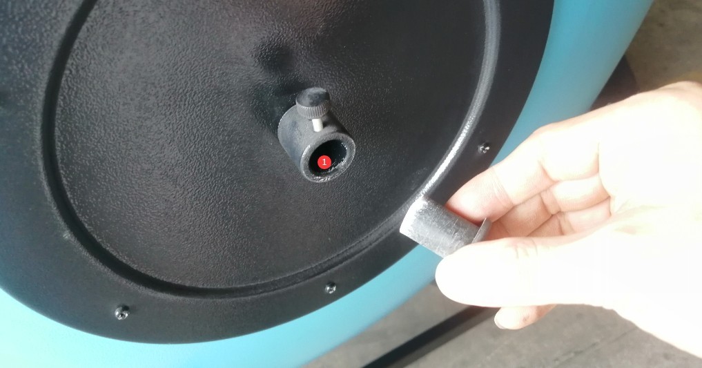
Figura 8-1
Locate the auxiliary light fixture, as shown in Figure 8-2:
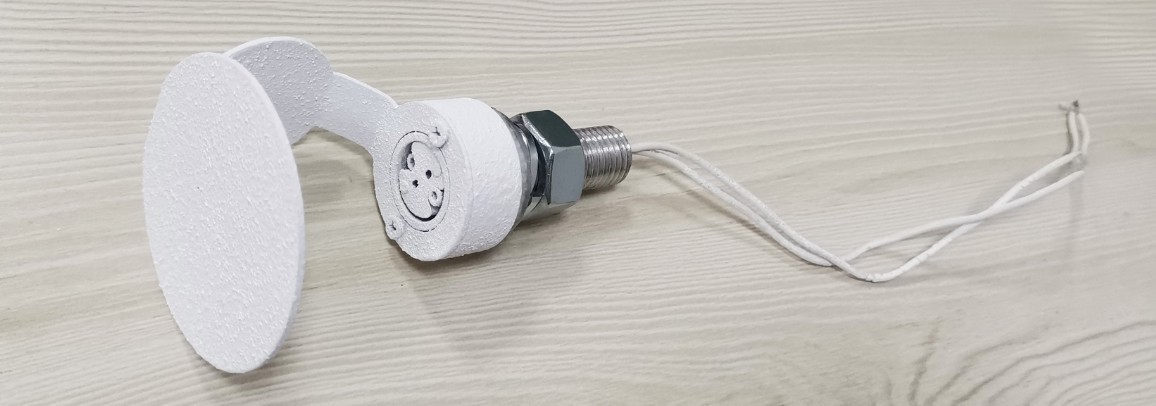
Figura 8-2
Remove the screws and washers, as shown in Figure 8-3:
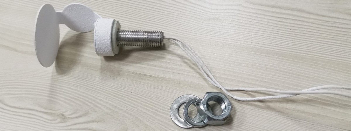
Figura 8-3
Feed the auxiliary light fixture out from the inside of Integrating Sphere, as shown in Figure 8-4:
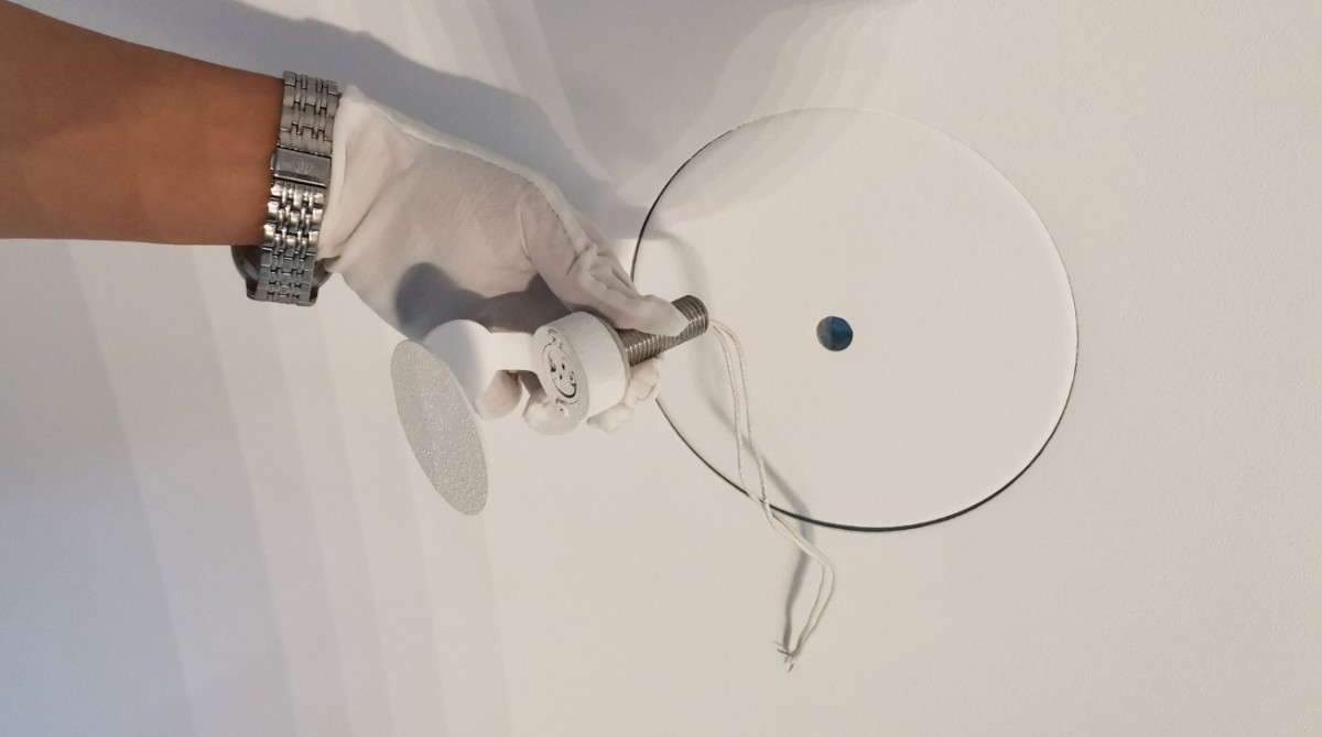
Figura 8-4
For auxiliary light wiring, see Figure 8-5.
| Numero | Note: |
| ① | Then secure the screws and washers to the outside of Integrating Sphere |
| ② | Please connect an extension cord with a banana plug to the side of the cabinet and keep it on hand. Note: We do not provide the wire connecting the auxiliary light to the DC power supply; we only provide the banana plug. Please find a wire of the appropriate length and make the connection yourself. |
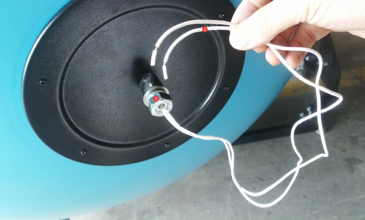
Figura 8-5
Adjust the length of the wire to ensure that Integrating Sphere can be properly connected to the front panel of the DC power supply, whether it is closed or open, as shown in Figure 8-6.
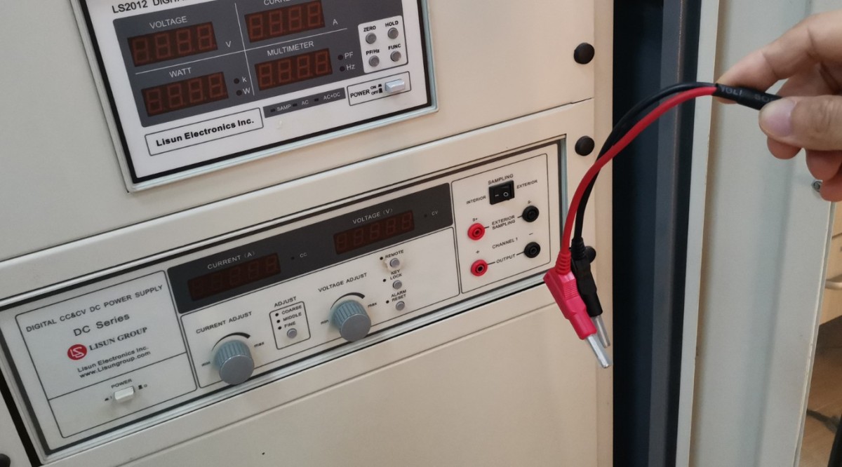
Figura 8-6
Please wear gloves, remove the auxiliary light bulb, and install it in the auxiliary light fixture, as shown in Figure 8-7.
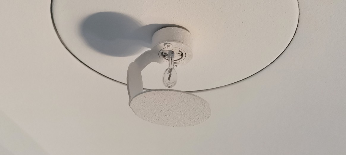
Figura 8-7
8.3 Steps for Generating the Self-Absorption Coefficient
Connect the auxiliary light power cord to the output terminal on the front panel of the DC power supply, as shown in Figure 8-8.
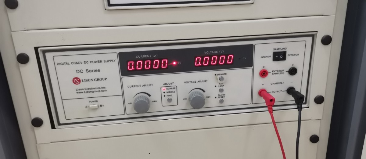
Figura 8-8
Go to the self-absorption coefficient interface, as shown in Figures 8 and 9.
| Numero | Note: |
| ① | Click “Self-Absorption Coefficient” |
| ② | Fare clic su "Aggiungi" |
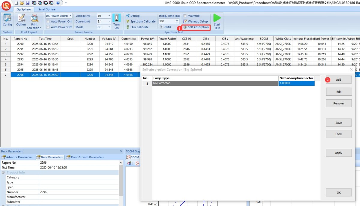
Figure 8–9
Generated from the absorption coefficient, Step 1; see Figures 8–10.
| Numero | Note: |
| ① | Enter the model number of the luminaire under test. If you test the same luminaire again later, you only need to select the corresponding correction factor from the list of self-absorption coefficients; there is no need to generate the correction factor again. |
| ② | A: If the DC power supply has successfully established communication in “System Configuration,” the correct DC power supply model and port number will automatically be displayed here; you can also click “Search” to rescan for the correct port . B: If you have not purchased a LISUN DC power supply or communication has not been established, please select “Not Installed” for the DC power supply model; otherwise, the software will display an error. |
| ③ | A: If the software has successfully communicated with the DC power supply, the auxiliary lamp data can be found on the packaging and the calibration certificate; enter the rated current and reference voltage . B: If the software has not successfully communicated with the DC power supply, there is no need to enter the current, voltage, or warm-up time ; generally, a 15-minute warm-up is sufficient. |
| ④ | Follow the instructions here for Steps 1 and 2. At this point, both the standard lamp and the auxiliary lamp are inside Integrating Sphere. The standard lamp must be installed exactly at the center of Integrating Sphere, but do not connect its power cord (it is used only to simulate the calibration environment). Then, turn off Integrating Sphere. If your device includes Integrating Sphere, turn Integrating Sphere off at the same time. |
| ⑤ | A: If the software has successfully established communication with the DC power supply, you can simply click “Start.”and the software will automatically control the DC power supply to illuminate the auxiliary light at a constant current, then enter the warm-up countdown . B: If the software fails to establish communication with the DC power supply, you must first manually control your DC power supply to illuminate the auxiliary light at a constant current, then click “Start” to enter the warm-up countdown. |
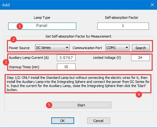
Figure 8–10
Generated from Step 2 of the absorption coefficient calculation; see Figures 8–11.
| Numero | Note: |
| ① | After the 15-minute warm-up period, the software proceeds to Step 2 of 2. Following the instructions here, open Integrating Sphere, remove the standard lamp, and place the lamp under test in the center of Integrating Sphere—but do not connect the power cord to the lamp under test (this is only for simulating the test environment). At this point, the auxiliary lamp remains on. Then close Integrating Sphere. |
| ② | Click “Finish.” The software will automatically calculate the self-absorption coefficient. |
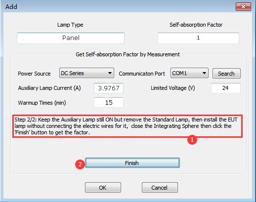
Figure 8–11
Autocorrelation coefficient generation; see Figures 8–12.
| Numero | Note: |
| ① | Self-absorption coefficient calculated automatically by the software |
| ② | Click “OK” to automatically save and exit the self-absorption coefficient generation interface. A: If the software has successfully communicated with the DC power supply, you can turn off the auxiliary light through the software. B: If the software has not successfully communicated with the DC power supply, you can manually turn off the DC power supply output. |
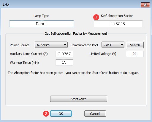
Figure 8–12
After using the auxiliary light, be sure to disconnect its power cord. If the auxiliary light will not be used for an extended period, allow it to cool down, then remove it and store it properly.
8.4 Test con il fattore di correzione della luce ausiliaria
During testing, the auxiliary light correction factor just generated will be used by default. Please refer to Chapter 6 for testing instructions.
Nota: le luci ausiliarie vengono utilizzate esclusivamente per generare fattori di correzione; si prega di non accenderle durante i test ufficiali.
9. Manutenzione e cura quotidiana delle attrezzature
Hardware 9.1
9.1.1 Manutenzione giornaliera
Before turning on the device, check that Integrating Sphere is closed and that there is no dust or debris inside; check that all connections are secure and that the USB cable and Optical Fiber are not damaged; after turning off the device, close Integrating Sphere, disconnect the main power supply, and wipe dust from the surface of the device.
9.1.2 Manutenzione settimanale
Open Integrating Sphere Integrating Sphere and use a hair dryer (set to the cool air setting) to blow out the dust from the inside out, preventing the dust from adhering to the coating; inspect the packaging of the standard lamp to ensure it is free of moisture and damage, and verify the expiration date.
9.1.3 Manutenzione mensile
Inspect the coating Integrating Sphere: If there is minor peeling, contact us to obtain coating repair materials; if there is extensive peeling, Integrating Sphere must be replaced.
9.1.4 Manutenzione annuale
Sostituite le lampadine standard (indipendentemente dal fatto che funzionino o meno; devono essere sostituite al termine del loro ciclo di vita).
9.2 Software
Aggiorneremo periodicamente il software per aggiungere nuove funzionalità e correggere eventuali bug. Qualora riscontraste problemi durante l'utilizzo del software, non esitate a contattarci in qualsiasi momento per ottenere la versione più recente.
9.3 Smantellamento e manutenzione a lungo termine
9.3.1 Pulizia e protezione delle apparecchiature
Thoroughly clean all equipment surfaces, and cover the cabinets and Integrating Sphere with dust-proof cloths; disconnect all power sources, and unplug power cords and communication cables.
9.3.2 Protezione ambientale
Ensure that the laboratory is dry and well-ventilated to prevent equipment from becoming damp. If the ambient humidity is high, keep a dehumidifier on hand.
9.3.3 Accensione mensile
Power on the system once a month to ensure that all hardware components are functioning properly.
9.4 Requisiti relativi all'intervallo di calibrazione
Per garantire la precisione delle misurazioni e l'affidabilità operativa dell'apparecchiatura, si raccomanda di inviarla periodicamente a un laboratorio metrologico terzo qualificato per la calibrazione. L'intervallo di calibrazione raccomandato è di 12 mesi. Gli utenti possono determinare l'intervallo di calibrazione specifico in base alla frequenza di utilizzo, alle condizioni ambientali e ai requisiti del sistema qualità.
10. Risoluzione dei problemi e delle problematiche comuni
10.1 Guasti di comunicazione hardware
Cause del problema: driver non installato o installazione non riuscita; connessione della porta USB errata; modello di dispositivo selezionato errato;
Troubleshooting Steps: Check the computer’s Device Manager to verify that the LMS-9000 and the four COM ports are functioning properly (no exclamation marks);
Reinstall the drivers (with antivirus software disabled) to ensure that both the communication box driver and the spectrometer driver are successfully installed; connect the USB cable directly to a native USB 2.0 or 3.0 port on your computer (do not use a USB hub or USB extension cable); go to “System Configuration” in the software, reselect the device model, and click “Search for Port.”
10.2 Errori di calibrazione
10.2.1 The standard lamp won’t turn on
Causes of malfunction: The AC/DC switch is not set to the DC position; “Auto-Light” is not checked on the calibration screen; incorrect voltage or current parameters; broken filament;
Troubleshooting Steps: Ensure the AC/DC switch on the cabinet is set to “DC” and that the standard lamp is securely connected; verify that “Auto Illumination” is checked on the calibration interface, and that the entered voltage and current match those specified in the standard lamp certificate; inspect the standard lamp filament—if it is broken or blackened, replace the standard lamp.
10.2.2 Calibration Prompt: “Signal Too Weak”
Causes of malfunction: Optical Fiber connected; Integrating Sphere lid not closed properly; standard lamp not lit; Optical Fiber kinked or broken;
Troubleshooting: Check that Optical Fiber is securely connected at both ends and is not excessively bent; close Integrating Sphere to ensure it is properly sealed and no external light is entering; verify that the standard lamp is lit; if it is not, follow the troubleshooting steps in Section 5.2; if Optical Fiber is broken, contact us for a replacement.
10.3 Anomalie nei dati di test
10.3.1 Dati di test inaccurati
Causes of malfunction: Failure to perform regular calibration, incorrect correction factor for the auxiliary lamp, improper selection of Integrating Sphere, damaged coating, or issues with the sample itself
Procedure: Recalibrate according to Chapter 5, ensuring the calibration interval is ≤ 1 week; set the correction factor to 1 for bare light sources and small luminaires, and use the correct correction factor for large luminaires; Use Integrating Sphere for large samples and a small Integrating Sphere for small samples to avoid size mismatches; if the Integrating Sphere Sphere’s coating is severely peeling or has significantly darkened, contact us for repair; test several additional sets of different sample types; if most results are acceptable, the issue lies with the sample itself.
10.3.2 Variazione eccessiva nei risultati dei test
Cause of the malfunction: Insufficient preheating time; severe sample flicker;
Solution: Extend the warm-up time (e.g., 20–30 minutes) and wait for the sample to stabilize before testing; use a flicker tester to check the sample for flicker issues.
10.3.3 I parametri elettrici vengono visualizzati come 0
Cause of the malfunction: Incorrect selection of the power meter model; incorrect wiring;
Troubleshooting Steps: Go to “System Configuration” in the software, select the correct power meter model, and rescan the ports; check the power meter wiring to ensure that A1, A2, V1, and V2 are connected correctly and securely.
10.4 Software Operation Errors
10.4.1 Il software non si avvia (nessuna risposta al doppio clic)
Cause of the problem: Not running as an administrator; incomplete software installation;
Solution: Right-click the software shortcut and select “Run as administrator”; uninstall the old software, delete any remaining folders, and then reinstall the software.
10.4.2 Software Fails to Open or Database File Error
Cause del problema: autorizzazioni software insufficienti, il percorso di salvataggio non esiste oppure il file è in uso;
Solution: Run the software as an administrator; create a new database file; do not save the database file directly to your desktop.
10.5 Interruzione dell'alimentazione
10.5.1 Anomalie dell'uscita di alimentazione CC
Cause del malfunzionamento: l'interruttore AC/DC sull'armadio non era impostato su DC; la tensione o la corrente del campione superavano i limiti dell'alimentatore DC; un cortocircuito nel campione;
Risoluzione dei problemi: Verificare che la tensione e la corrente del campione rientrino nell'intervallo di uscita dell'alimentatore CC. Ad esempio, DC3005 Il modello ha una tensione di uscita massima di 30 V e una corrente di uscita massima di 5 A. Verificare se il campione è in cortocircuito; in tal caso, riparare il campione prima di ripetere il test.
10.5.2 Nessuna uscita CA
Cause of the malfunction: The AC/DC switch on the cabinet was not set to the AC side, and the overload protection was triggered;
Troubleshooting Steps: Check the AC power output wiring and sample connections to ensure there are no loose connections or short circuits; if the overload protection is triggered, turn off the power, let the unit cool for 5 minutes, and then restart it. Ensure that the sample power remains within the AC power output range—for example, the LSP-500VARC ha una potenza di uscita massima di 500 W.